1 Introduction
This document describes all aspects of handover in a Wideband Code Division Multiple Access Radio Access Network (WCDMA RAN) system.Handover occurs as User Equipment (UE) moves between cells with connection quality maintained with as little radio resource usage as possible. The following types of handover are described:
- Soft/Softer Handover
- Inter-Frequency Handover
- Inter-Radio Access Technology (Inter-RAT) Handover or Cell Change
- Core Network Hard Handover
- Service Based HO to GSM
- HSDPA (and EUL) mobility
Mobility procedures for the HSDPA and Enhanced UL features are also included. HSDPA introduces a new downlink transport channel, the High Speed Downlink Shared Channel (HS-DSCH), see HSDPA Overview. It provides connected mode mobility control in CELL_DCH state for any radio connection used to setup and maintain radio bearers for HSDPA.
1.1 Target Groups
This target groups for this document is the following groups of personnel:- System operators that need a general understanding of Handover in WCDMA RAN.
- Personnel working on Ericsson products or systems.
1.2 Revision Information
Apart from editorial changes, this document has been revised according to Table 1.| Revision | Reason for Revision |
|---|---|
| A | This document is based on 76/1553–HSD10102/6 rev C. The following functionality has been added: - EUL 2 ms TTI functionality - IF and IRAT mobility on HSDPA / EUL. |
2 Overview
2.1 Soft/Softer Handover
In Soft Handover, the UE connection consists of at least two radio links established with cells belonging to different RBSs. In Softer handover, the UE connection consists of at least two radio links established with cells belonging to the same RBS. A combination of Soft and Softer Handover is also possible for a UE connection. Thus the UE active set (see definition in Section 3.3) may include radio links established to cells of different RBSs and radio links established to cells of the same RBS. At least one radio link is always used for maintaining the connection by fast power control, see Power Control. Data flow is not interrupted during the addition or removal of radio links. The downlink signals, received by the UE, are combined in the RAKE receiver; that allows for multipath reception and thereby gives protection against fading.Using soft and softer handover, combined with fast power control, all cells can use the same frequency (frequency reuse of 1). Soft and softer handover allows shifting the cell controlling the connection uplink and downlink power levels without using layer 3 RRC signaling, as this is too slow, since the best serving cell is shifted very fast due to fading. This is crucial avoid disturbing cells with the UE transmission when using the same frequency during fading conditions at the cell borders.
- Note:
- Fast fading for UL and DL is independent and therefore at least one radio link in UL and one in DL needs to work to close the loop for the fast power control.
The UE and the WCDMA RAN must achieve a connection that has a sufficient Signal-to-Interference Ratio (SIR), even when the UE is at the cell border. The UE requires enough power to achieve sufficient downlink SIR . Using Soft or Softer Handover, the UE takes advantage of having several simultaneous radio links, as shown in Figure 1, and the DL RBS's output power can be lowered, reducing interference and increasing maximum possible system capacity. This advantage is possible since the UE performs maximum ratio combining of the downlink. In the downlink, the signals from the different RBSs are received in the UE and combined in the RAKE receiver. The RAKE receiver buffers these signals according to their delay, decodes them, and performs maximum ratio combining. This gives protection against fading, and macro-diversity and multipath diversity gain can be obtained depending on radio conditions and consequently the RBS output power can be lowered while maintaining sufficient connection quality.
In Soft/Softer Handover the network takes advantage of having several simultaneous radio links by using, in case of Soft Handover, the selection combining, and in case of Softer Handover the maximum ratio combining, performed at the RAKE receiver implemented in the RBSs. Thus the UL power emitted by the UE can be lowered, reducing UL interference and increasing maximum possible system capacity.
- Note:
- There is a trade off between using many radio links for one UE connection as compared to reducing each radio link power by achieving diversity gain.
- Without Soft/Softer Handover, at the edge of the RBS_A cell, see Figure 1, the UE would transmit on full power for UL, and the fast power control would not be able to compensate fully for fast fading. The UE transmitting on full power would cause UL interference in RBS_B cell, reducing the capacity of RBS_B cell. With Soft/Softer Handover, the UE can transmit at lower power, since it is power controlled by both cells, RBS_A cell and RBS_B cell, reducing interference and increasing maximum system capacity. However, there is a trade-off between Soft/Softer Handover and system capacity. A UE involved in Soft/Softer Handover uses several radio links, more DL channelization codes, and more DL power than a single-link connection. Consequently, if all the UEs connected to a particular RNC are considered, more resources are needed in the RBSs, more resources over the Iub and Iur interfaces, and more resources in the RNC. For this reason, the number of radio links involved in the Soft/Softer handover must be limited. Radio network planning and optimization must determine the size of the handover areas between the cells. There is also a means of protection from UEs becoming severe disturbers. Imagine the following scenario: a UE entering a new cell area being covered by a cell that the UE has not been ordered to measure and report on. This scenario may cause severe uplink interference for the other users connected to that cell. In order to detect and avoid interference situations like this, according to 3GPP, the UE can be ordered to report Detected Cells. If a reported Detected Cell is not possible to add to the Active Set and the UE is considered to cause significant interference, the connection will be released in order to avoid the UE staying in that cell area without being power controlled by the Power Control function of that cell.Figure 1 Macrodiversity
2.2 Inter-Frequency Handover
Inter-Frequency Handover prevents dropped calls and thus allow for service continuation on dedicated channels when the UE is moving out of coverage of one WCDMA RAN frequency to an area where coverage on another WCDMA RAN frequency exists. IFHO can also be triggered when performing cell selection for a packet connection.2.3 Inter-RAT Handover
Inter-RAT Handover prevents dropped calls and thus allow for service continuation on dedicated channels for circuit-switched services when the UE is moving out from WCDMA RAN coverage to an area where only GSM network coverage exists.2.4 Service Based Handover
Service Based Handover forces UE on dedicated channels using a “speech only” service, to move from WCDMA RAN coverage to GSM network coverage; thus allowing the operator to redirect speech users to GSM using a Service Indicator (SI) that can be set per subscriber. The feature is activated at RNC level.2.5 Inter-RAT Cell Change
Inter-RAT Cell Change prevents dropped calls and thus allow for service continuation on dedicated channels for Packet-Switched-services when the UE is moving out from WCDMA RAN coverage to a GSM network coverage area. Inter-RAT Cell Change is network initiated for dedicated channels. For common channels Inter-RAT Cell Reselection is used, see Idle Mode and Common Channel Behavior.2.6 Core Network Hard Handover
Core Network Hard Handover supports both Intra and Inter frequency Hard Handover to a cell in another RNS (different from the SRNS and the DRNS) towards which the SRNC does not have any Iur connectivity, when the UE is only using Circuit Switched services. Any active Packet Switched service will be released and typically re-established after the Core Network Hard Handover execution.2.7 HSDPA Mobility
The mobility procedures are based on the concept that the HS-DSCH allocation for a given UE belongs to only one of the radio cells assigned to the UE, the serving HS-DSCH radio link. The cell associated with the serving HS-DSCH radio link is defined as the Serving HS-DSCH cell. The main purpose of HSDPA mobility is to handle serving HS-DSCH cell change. The connection also uses A-DCHs which are handled by soft/softer HO in the normal way. See HSDPA Overview. Mobility might also trigger a reconfiguration from HS-DSCH to DCH in the cases where a serving HS-DSCH cell change cannot be done, or if bad coverage is detected. While using a packet interactive service, an upswitch attempt to HS-DSCH can be triggered by activity, that is throughput measurement. The HS-DSCH mobility function is able to operate in an environment where certain cells are not equipped or configured to support HS-DSCH . Moreover, it is designed to operate in an environment in which not all UEs are capable of HSDPA.2.8 HSDPA and EUL Mobility
If EUL is supported in the network, EUL mobility works in the same way as HSDPA mobility and is triggered by the same cases. In addition there are some new cases when a UE leaves EUL coverage and when handling E-DCH soft/softer HO. The serving EUL and HSDPA cells are always the same, and EUL is always used together with HSDPA.2.9 Connection Quality Monitoring
Connection Quality Monitoring consists of DL quality measurements based on P-CPICH Ec/No and P-CPICH RSCP running in parallel, and of UL UE Tx power measurements. Either of these measurements might trigger the start of an inter-frequency or an Inter-RAT handover. Before inter-frequency handover starts, fulfillment of the minimum quality for both Ec/No and Rscp for the target cell is checked. It is anyway possible, as a configuration option, to set the parameter values so that either of these measurements are activated or deactivated. If the 2d event trigger decision is currently based on Ec/No measurements, the parallel RSCP measurement could be initially disabled by setting timeToTrigger2dRscp to 5000 [ms]. If the 2d event trigger decision is currently based on RSCP measurements, the parallel Ec/No measurement could be initially disabled by setting timeToTrigger2dEcno to 5000 [ms]. The UE Tx power monitoring can be disabled with the parameter txPowerConnQualMonEnabled. A setting of utranRelThreshRscp to 0 [dB] would make the uplink monitoring similar to previous functionality for the case when bad uplink quality is triggered and a RSCP based measurement is started.- Note:
- These settings will affect, both Inter-Frequency and Inter-RAT Handover evaluation at the same time.
2.10 Frequency Handling
The following frequency bands are functionally supported, provided that the RBS and the UEs have the corresponding capability. Refer to 3GPP 25.101.
The relation between the used carrier frequencies and the corresponding 3GPP frequency band should be defined. Due to potential overlaps between the bands, the HO algorithms need to know this relation for overlapping bands. This can be defined with the parameters freqBand and uarfcnDl, for each RNC and for each used carrier. These definitions are necessary if the system contains more than one of the above 3GPP frequency bands, but can be omitted if only one band is used. Also refer to Multiband Operation Note that for DRNCs the defaultHoType parameter should be defined. This parameter controls if Interfrequency HO, IRAT HO or no compressed mode or IF/IRAT HO can be triggered in external cells, for each DRNC and for each carrier. For example, to disable compressed mode in all external DRNC cells this parameter should be set to NONE.Table 2 Frequency Bands in the 3GPP release 7 specifications 3GPP Band UL (MHz) DL (MHz) Width (MHz) Duplex (MHz) I 1920 – 1980 2110 – 2170 60 190 II 1850 – 1910 1930 – 1990 60 80 III 1710 – 1785 1805 – 1880 75 95 IV 1710 – 1755 2110 – 2155 45 400 V 824 – 849 869 – 894 25 45 VI 830 – 840 875 – 885 10 45 VII 2500 - 2570 2620 - 2690 70 120 VIII 880 - 915 925 - 960 35 45 IX 1749.9 - 1784.9 1844.9 - 1879.9 35 95 X 1710 - 1770 2110 - 2170 60 400 2.11 Quality of Service aspects
Quality of Service and different types of priorities are supported for different types of connections. This is used by Capacity Management to prioritize between connections when system resources becomes scarce. The mobility aspects are that QoS configurations for the Radio Network and the Transport network should be made for connections that are setup by incomming HO over Iur, or incomming HO from GSM. Refer to QoS Configurations for further details.3 Technical Overview and Concepts Used
This section gives a technical overview and explains 3GPP-defined measurement handling concepts used for supporting Soft/Softer Handover, Inter-Frequency Handover, Inter-RAT Handover (including the particular case of Service Based Handover), Inter-RAT Cell Change, Hard Handover via Core Network, and serving HS-DSCH Cell Change.. Furthermore the basic concepts related to the HSDPA mobility features are briefly illustrated. Soft/Softer Handover, Inter-Frequency Handover, Inter-RAT Handover (including the particular case of Service Based Handover), Inter-RAT Cell Change, Hard Handover via Core Network, and serving HS-DSCH Cell Change all consist of an evaluation part and an execution part. The evaluation part initiates and evaluates UE measurements on neighbor cells. The execution part, triggered by the evaluation results, allocates resources (if necessary) and performs the actual Handover (including serving HS-DSCH Cell Change) or Inter-RAT Cell Change. Figure 2 shows the entities involved during the reporting, evaluation, and execution phases.- Note:
- Shaded entities correspond to related functions not described in this document.
- SHO_Eval: Soft/Softer Handover evaluation algorithm.
- IFHO_Eval: Inter-Frequency Handover evaluation algorithm.
- IRATHO_Eval: Inter-RAT Handover (WCDMA RAN to GSM) evaluation algorithm.
- SBHO_Eval: Service Based Handover (WCDMA RAN to GSM for speech users only) evaluation algorithm, as a particular case of IRATHO algorithm.
- IRATCC_Eval: Inter-RAT Cell Change (WCDMA RAN to GSM) evaluation algorithm.
- CNHHO_Eval: Hard Handover via Core Network evaluation algorithm.
- HSCC_Eval: Serving HS-DSCH Cell Change evaluation algorithm.
- Meas_Handl: Measurement handling algorithm.
- UE_Meas_Eval: UE measurement evaluation algorithm (working in the UE).
- Soft/Softer Handover: filterCoefficient1.
- Connection Quality Monitoring: filterCoefficient2, filterCoeff6.
- Inter-Frequency Handover: filterCoeff4_2b.
- Inter- RAT Handover: utranfilterCoefficient3, gsmFilterCoefficient3.
- Note:
- Note that it is not allowed to have more than 2 different filter coefficients for the same type of physical Layer 1 measurements: for example filterCoefficient1, filterCoefficient2, and filterCoeff4_2b may have only 2 different values, one for the intra-frequency and one for the inter-frequency measurements, according to 3GPP standard.
- Soft/Softer Handover: w1a, w1b.
- Connection Quality Monitoring: usedFreqW2d, usedFreqW2f.
- Inter-Frequency Handover: usedFreqW4_2b, nonusedFreqW4_2b.
- Inter-RAT Handover: utranW3a.
- WCDMA RAN may ask the UE about its access capability by sending a UE CAPABILITY ENQUIRY message, then the UE must respond with the UE CAPABILITY INFORMATION message.
- When the UE capability changes while the UE is in connected mode, the UE must send the UE CAPABILITY INFORMATION message to inform WCDMA RAN about changed capabilities.
- Intra-Frequency adjacent cells Any WCDMA RAN cell may have up to 31 intra-frequency cell relations. Each cell relation consists of a pair of cells, the source cell and the target cell. The source cell has a relation to the target cell. That is, when the UE has the source cell in its Active Set, then the target cell is considered as neighbor cell.
- Inter-Frequency adjacent cells Any WCDMA RAN cell may have up to 64 Inter-Frequency adjacent cells. Each cell relation consists of a pair of cells, the WCDMA RAN source cell and the WCDMA RAN target cell on another frequency. The source WCDMA RAN cell has a relation to the target cell. That is, when the UE has the source WCDMA RAN cell in its Active Set and the event 2d occurs (measured WCDMA RAN quality is below certain threshold), then the target cell is considered as neighbor cell.
- Inter-RAT adjacent cells Any WCDMA RAN cell may have up to 32 Inter-RAT adjacent cells. Each cell relation consists of a pair of cells, the WCDMA RAN source cell and the GSM target cell. The source WCDMA RAN cell has a relation to the GSM target cell. That is, when the UE has the source WCDMA RAN cell in its Active Set and the event 2d occurs (measured WCDMA RAN quality is below certain threshold), then the target cell is considered as neighbor cell.
- Note:
- A priority has been introduced for neighbor cell relations. The parameter selectionPriority can be set for each defined neighbor, where a value of one means the highest priority. If the same priority is used for several neighbor cells, the order between them is not defined. If no value or a value of zero is entered when a neighbor is defined, the system will automatically set it to the currently highest used value of selectionPriority, + 1, that is, to the currently lowest priority definition for the source cell and for the relation type (Intra / Inter / GSM).This priority can be set separately for intra, IF and GSM neighbors.
- A-DCH: Associated Dedicated Channel: Dedicated channels in up-link and down-link associated to the HS-DSCH channel.
- E-DCH: Enhanced Uplink Dedicated Channel.
- “Best Cell”: Active Set cell with the best quality based on the latest UE reported Primary CPICH measurements.
- Serving HS-DSCH cell: The cell within the active set that transmits HSDPA data in DL to a UE.
- Serving EUL cell: The cell within the active set that controls the scheduling of the EUL data. Always the same as the serving HS-DSCH cell.
- Suitable HS-DSCH Cell:
- Cell in the current Active Set.
- Cell having HS-DSCH enabled.
- Suitable EUL Cell:
- Algorithms for handling Cell Sets, Subsets and Lists Determines the subset of cells to be measured on by the UE based on the cells present in the active set and the configured neighboring cells for the cells in the active set
- Soft and Softer Handover Evaluation Evaluates which cells should be proposed to be added, removed, or replaced in the Active Set. The algorithm bases its decision on quality measures of the P-CPICH done in the UE. An evaluation that results in a revised Active Set proposes it to the execution part of Soft/Softer handover.
- Soft and Softer Handover Execution Covers the actual addition and/or removal of radio links proposed by the Soft and Softer Handover Evaluation algorithm.
- Listed Set: The sum of the Active Set and the Monitored Set cells, that is, all cells, that WCDMA RAN explicitly orders the UE to measure on.
- Neighbor Set: The union of the neighboring cells of the cells in the Active Set excluding the cells in the Active Set. The Neighbor Set is divided in: IAF (Intra-Frequency) Neighbor Subset, IEF (Inter-Frequency) Neighbor Subset, GSM Neighbor Subset.
- Unmonitored Set: Cells in the Neighbor Set that the UE is not ordered explicitly to measure on.
- Proposed Active Set: A new Active Set proposed by Soft/Softer Handover Evaluation to Soft/Softer Handover Execution.
- IAF Monitored Subset Cells: The subset of WCDMA RAN cells that UE measures on.
- IAF Unmonitored Subset Cells: The subset of WCDMA RAN cells reduced from the original IAF Neighbor Subset due to subset reduction.
- IEF Monitored Subset Cells: The subset of WCDMA RAN cells on a non-used frequency that UE measures on.
- IEF Unmonitored Subset Cells: The subset of WCDMA RAN cells reduced from the original IEF Neighbor Subset due to subset reduction.
- GSM Monitored Subset Cells: The subset of GSM cells that UE shall measure on.
- GSM Unmonitored Subset Cells: The subset of GSM cells reduced from original GSM Neighbor Subset due to subset reduction.
- Neighbor Cell List: The list of cell relations for a particular cell, stored in the SRNC for each cell.
- Valid cell: A cell that is part of the Active Set, Monitored set or the Unmonitored set, the SRNC is able to translate information about reported P-CPICH scrambling code to a configured cell by using the configured neighbor cell lists.
- Invalid cell: A cell that is not part of the Active Set, Monitored set or the Unmonitored set, the SRNC does not have information for P-CPICH scrambling code translation to a configured neighboring cell.
 Figure 2 Entities Involved in Reporting, Evaluation, and Execution of Handover-Related Functions
3.1 Evaluation and Measurement Handing
The concept of event-triggered reporting as specified in 3GPP is used by handover evaluation and allows the UE to do part of the evaluation. UEs are configured to evaluate and send measurement reports to the system only when certain events occur, that is, when a monitored cell is measured and the measurement result for a monitored cell fulfills certain criteria. When the conditions for triggering a certain handover are fulfilled, the handover evaluation part triggers the corresponding handover execution part. Due to limitations in the Compressed Mode gap patterns used (see definition in Section 3.6), measurements for Inter-Frequency Evaluation and Inter-RAT Evaluation is not performed simultaneously. A decision has to be made whether evaluation should be made for Inter-Frequency handover or Inter-RAT handover or cell_change. The type of handover to be attempted is set by the parameter hoType (IFHO_PREFERRED, GSM_PREFERRED, NONE) configurable per cell, or per carrier frequency for external DRNC cells ( defaultHoType). Note that the Inter Frequency CNHHO_Eval is a part of IFHO_Eval and is made only if hoType / defaultHoType is set to IFHO_PREFERRED. The measurement quantity used for Soft/Softer HO, IF HO, IRAT HO, CNHHO, and serving HS Cell Change could be either P-CPICH Ec/No or RSCP. The system is configured by default to use P-CPICH Ec/No as the measurement quantity for Soft/Softer HO and Intra Frequency CNHHO, while RSCP is used as default for for serving HS CC. For IF HO (including IF CNHHO) and IRAT HO the connection quality is monitored for both P-CPICH Ec/No and RSCP in DL and for UE TX power in UL. If bad connection quality is triggered, the measurement quantity for IF HO or IRAT HO is set to Ec/No or RSCP depending on which measured quantity of the connection that was bad (see Section 5.1). For SBHO, the triggering condition does not take into account any UTRAN quality issues, and considers only the GSM target cell quality. If an Inter-RAT handover is triggered by the SBHO feature, the UTRAN connection quality is always considered bad, and the handover evaluation is based only on the quality of the GSM target cell.3.2 Measurement Handling (Meas_Handl)
The Measurement Handling algorithm prepares a list of cells that the UE will measure on. The algorithm prepares a message to send to the UE containing the measurement criteria, as well as the list of cells to measure on, in accordance with the handover parameters defined by the operator and the cells currently used in the active set (see definition in Section 3.3). When the UE is setup on a dedicated channel, during the RRC signaling connection establishment, the SRNC sends a MEASUREMENT CONTROL message, with "setup" indicator to the UE. This message is the first MEASUREMENT CONTROL message the UE receives for this particular connection and it contains the list of cells and the measurement criteria to be used. The list of cells and the measurement criteria for support of Soft/Softer handover are also broadcast in the system information on the BCCH channel, in SIB11/SIB12. This allows the UE to start Intra frequency measurement on configured neighbors Intra frequency for the cell where the RRC connection was setup before receiving the MEASUREMENT CONTROL message from the SRNC. As soon as a measured cell, or other measured quantities, fulfills the event-triggered condition, an event occurs, and the UE sends a MEASUREMENT REPORT message to the SRNC indicating which event occurred and which cells fulfilled the event criteria among those measured. Depending on the event, additional measurements can be started. After a successful handover the list of cells to measure on is typically updated by the SRNC. The Measurement Handling for the CNHHO needs to distinguish, within the Intra and Inter frequency monitored subset cells, two different groups: the ‘Normal’ UTRAN cells (belonging to the same RNC or to RNCs’ towards which an Iur connectivity is configured) and the ’Non-Iur External’ UTRAN cells (belonging to an RNC towards which no Iur connectivity is configured). Intra Frequency CNHHO is based on the fact that the ’Non-Iur External’ cells, now belonging to the Monitored Set, never can be included in the Active Set, and will cause Soft/softer Handover triggered reporting events. Inter Frequency CNHHO uses the same quality supervision events for starting and stopping Compressed Mode as for 'Normal' Inter Frequency Handover; and 'Non-Iur External' cells and normal neighbours are evaluated in the same way. When the UE is using a PS Interactive on DCH or on HS-DSCH, the MEASUREMENT CONTROL orders an extra event that supports serving HS-DSCH Cell Change, event 1 d HS, to be reported by the UE. No differences are introduced in the measurement support for A-DCH or E-DCH Soft and Softer Handover with respect to the conventional Soft and Softer Handover procedures.3.3 3GPP-defined UE Associated Cell sets for Measurement
The Measurement Handling algorithm determines the set of cells to be measured and evaluated by the UE based on the Active Set cells on the currently used frequency. The cells in a WCDMA RAN are, from UE point of view, divided in different mutually excluding sets defined by 3GPP.
The cells measured by the UE are the sum of the Active Set and the Monitored Set. The neighboring cells, which are configured, could be cells on the currently used WCDMA RAN frequency (Intra-frequency cells), cells on other WCDMA RAN frequencies (Inter-Frequency cells) and cells on GSM frequencies (Inter-RAT cells). Depending on the frequencies of the cells in the Monitored Set, intra-frequency WCDMA RAN measurements, Inter-Frequency WCDMA RAN measurements and Inter-RAT measurements are initiated in the UE. The number of Intra-frequency cells in the Monitored Set + the Active Set cells is limited by 3GPP to 32. The number of Inter-Frequency cells in the Monitored set is limited to 32. The number of Inter-RAT cells in the Monitored set is limited to 32.Active Set The cells involved in soft handover and measured by the UE Virtual Active Set The Active Set associated with a non-used frequency for support of Inter-Frequency evaluation Monitored Set The cells only measured by the UE and not part of the Active Set. The monitored set can consist of intra-frequency, Inter-Frequency and Inter-RAT cells Detected Set The intra frequency cells (P-CPICH scrambling codes) detected by the UE but not part of Active Set or monitored set 3.4 Hysteresis and Time to Trigger Concept
To limit the amount of event-triggered reports by avoiding event triggering for insignificant measurement fluctuations, an hysteresis parameter may be connected with reporting event given above. The value of the hysteresis is given to the UE in the reporting criteria field of the MEASUREMENT CONTROL message that SRNC sends to UE when the UE enters CELL_DCH state. In general, for any event with an associated hysteresis, the condition to trigger the event and thus to make the UE send a MEASUREMENT REPORT message indicating to WCDMA RAN that the particular event occurred, is that the measured signal remains above or below (depending on the event) the predetermined threshold plus/minus (depending on the event) half the hysteresis value, during a time equal or greater than the corresponding time to trigger. In general to re-trigger the same condition and cell again, the measured value needs to go below the threshold minus half the value of the corresponding hysteresis and back up again above the threshold plus half the value of the corresponding hysteresis.3.5 Filtering, Offsetting, and Weighting before Reporting
The measured values are filtered by the UE before comparing the result values with the event report criteria. There are two levels of filtering, Layer 1 filtering and Layer 3 filtering. Layer 1 filtering is done on the physical layer, while Layer 3 filtering is done by software averaging, according to 3GPP 25.133 standard. If the Information Element (IE) "Filter coefficient" is received, the UE applies filtering of the measurements for that measurement quantity according to the formula below. The filtering must be performed by the UE before UE event evaluation. The UE must also filter the measurements reported in the IE “Measured results”. The Layer 3 control of filtering does not apply to the measurements reported in the IE “Measured results on RACH” and for cell re-selection in connected or idle mode. The filtering is performed according to the following formula: Fn = (1–a) F n-1 + a M n The variables in the formula are defined as follows:
The following configurable parameters are used to set the k value:Fn The updated filtered measurement result. Fn-1 The old filtered measurement result. Mn The latest received measurement result from physical layer measurements, the unit used for Mn is the same unit as the reported unit in the MEASUREMENT REPORT message send by UE to WCDMA RAN, in the system it is configured by default to be Ec/No. a = 1/2 (k/2), where k is the parameter received in the IE "Filter coefficient".
The sampling rate the UE should use when translating the filter coefficient to an actual filter implementation is the measurement period stated for each measured quantity in the 3GPP standard. In order to initialize the averaging filter, F0 is set to M1 when the first measurement result from the physical layer measurement is received.
Regarding offsetting, an offset can be assigned to each cell. Either positive or negative, it is added to the measurement quantity before the UE evaluates whether an event has occurred. The UE receives the cell offsets for each cell in the MEASUREMENT CONTROL message sent from the SRNC to the UE. By applying a positive offset, the UE sends a MEASUREMENT REPORT message back to the SRNC as if the measured value is offset higher than reality. By applying a negative offset, the UE considers the measured value to be offset lower than reality at event evaluation. The configurable parameter individualOffset is used for this purpose, and it is configured for each WCDMA RAN Cell.
Regarding weighting, a weighting factor is used to include active set cells other than the best in evaluation criteria for reporting events. The following configurable parameters apply as weighting factors:
3.6 Compressed Mode
Compressed Mode Control is a mechanism whereby certain idle periods are created in radio frames during which the UE can perform measurements on other frequencies. The UE can carry out measurements in the neighboring cell, such as GSM cell and FDD cell on another frequency.
Compressed Mode Control handles UL and DL independently, thus compressed mode can be used in DL only, UL only, or both UL and DL depending on the UE capabilities.
Compressed Mode is used as soon as the UE requires Compressed Mode for any of the GSM bands that it supports to avoid having to check and possibly start/stop Compressed Mode at Active Set updates.
Two different methods, HLS or SF/2, are used to create these idle periods depending on the radio bearer combination.
In case of HLS, the idle periods are created by higher layers (that is, layer 2) that set restrictions so that only a subset of the allowed TFCs are used in the compressed radio frames, thus reducing the user data throughput.
In case of SF/2, the idle periods are created by using a channelization code from the alternate code tree, corresponding to a spreading factor equal to half the one that is normally used and thus using more radio resources, that is, power and code to transmit the normal amount of user data.
3.7 UE Capability Handling
Depending of the UE radio access capability contained in the UE CAPABILITY INFORMATION message sent to WCDMA RAN, the UE support for measurements is known by WCDMA RAN. By knowing the UE support WCDMA RAN is able to handle the UE in an appropriate way in relation to handover.
There are two situations in which the UE sends its capability information:
The UE Capability regarding frequency band support is also checked for incoming HO attempts from GSM.
3.8 Adjacent Cell Configuration
Adjacent cell configuration is needed for handover and Cell Reselection purposes. During the network design process cell relations are defined. Adjacent cells are defined after studying desired soft/softer handover areas, and the areas where the WCDMA RAN coverage becomes weaker and GSM coverage exists. Three kinds of adjacent cells can be defined:
Adjacent cells can be defined using OSS-RC. Cell relations and cell relation parameters are broadcast in BCCH, in System Information Distribution. So the UEs in idle mode can be aware of adjacent cells and the criteria for measuring and reporting. As soon as the UE is in connected mode, a MEASUREMENT CONTROL message is sent to UE containing the measurement criteria the UE must use for measuring on other cells and the reporting criteria that the UE must use for reporting events to the SRNC.
3.9 HSDPA and EUL Mobility Concepts
The following basic concepts are involved in the HSDPA and EUL mobility features:
4 Soft and Softer Handover
Soft and Softer Handover can be split into three main parts
4.1 Algorithms for Cell Sets and Lists
4.1.1 Cell Sets, Subsets and Lists
The cells in a WCDMA RAN are, from a 3GPP and UE point of view, divided in different sets , Active Set, Virtual Active Set , Monitored set and Detected set see Section 3.3. In the Ericsson Handover implementation, the following additional sets and subsets are considered:
 Figure 3 Overview of Sets and Subsets of Cells
4.1.2 Monitored Set Creation
After the UE has entered state CELL_DCH or after the Active Set is updated (including successful IFHO), the Monitored Set is created. It is based on the neighbor cells of the cells in the Active Set and is typically updated when the Active Set is updated.
The Monitored Set consists of three subsets namely
The neighboring cell lists is PLMNid Access filtered based on IMSI and PLMNid if SelHoSup is ’TRUE’. The neighboring cell lists is further filtered based on UE capabilities information and also reduced in size by Monitored subset reduction to create the Listed set sent to the UE.
PLMNid Access Filtering of Neighbor Cell Lists
Also refer to Shared Network.
In order to limit the cells that the UE shall measure on for handover, the configured neighbor Cell Lists are access filtered. This is done so that after the filtering only cells that are allowed for handover are included in the Access Filtered neighbor Cell Lists. One type of access filtering is possible, namely PLMNid Access Filtering. The filtering is described below. A cell that is removed by this filtering does not belong to the Unmonitored subset, and is never added to the Active Set even if a detected set event report with this cell is received. PLMNid access filtering is performed in the SRNC on the unfiltered neighbor Cell Lists. The steps below are performed.
- If selective handover is disabled ( SelHoSup is False), no PLMNid Access Filtering is done. The PLMNid Access Filtered neighbor Cell List is equal to the unfiltered neighbor Cell List
- If the UE IMSI is not available, then no PLMNid Access Filtering is done. The PLMNid Access Filtered neighbor Cell List is equal to the unfiltered neighbor Cell List.
- If the UE IMSI is available, extract the Home PLMNid from the UE IMSI.
- Check if the UEs Home PLMNid is defined as a target PLMNid in any PLMN alias table. If yes then keep all defined neighbor cells belonging to this PLMN.
- Check if the UEs Home PLMNid is defined as an alias PLMNid in any PLMN alias table. If yes, then extract the corresponding defined target PLMNid(s). Keep all defined neighbor cells belonging to the target PLMN(s).
- If the UEs Home PLMNid is not defined as an alias or target PLMN within any alias table, then no PLMNid Access Filtering is done. The PLMNid Access Filtered neighbor Cell List is equal to the unfiltered neighbor Cell List.
UE Capability Filtering of Neighboring Cell Lists
Ue capabilities must be evaluated to obtain what GSM bands that the Ue supports. The PLMNid access filtered GSM Neighbor Cell List is created by removing from the PLMNid access filtered Neighbor Cell List, the neighboring cells corresponding to GSM frequency bands not supported by the UE. The frequency bands supported by UTRAN are GSM 850, GSM 900, GSM/DCS 1800 and GSM/PCS 1900. The GSM/DCS 1800 band and the GSM/PCS 1900 band have overlapping frequencies (ARFCN's). The Band Indicator indicates whether the ARFCN's are for the GSM/DCS 1800 band or for the GSM/PCS 1900 band. The Band Indicator must be retrieved from the external GSM cell definition and sent to the Ue in MEASUREMENT CONTROL message when ordering GSM measurements.
This Band Indicator should normally be set to DCS1800 as a default. For the PCS/GSM1900 band or for the GSM850 band the Band Indicator should be set to PCS1900. For the case when there are dual GSM bands 850/1800, the Band Indicator for the GSM850 band should be set to DCS1800.
Cells using frequencies from unsupported bands will not be sent to a Ue as interfrequency neighbor cells. It is assumed according to the standard that a Ue supports all frequencies within the current band
Monitored Subset Reduction
The maximum number of cells that a UE is required to measure according to 3GPP specification is 32 of each type (Intra-Frequency, Inter-Frequency and GSM cells). The maximum number of cells in a Monitored Subset, supported by WCDMA RAN, is a variable that is related to a configurable parameter for each type of neighbor cells (IAF, IEF, and GSM). The variable is denoted MaxMonSubset in the descriptions below. The relation to the configured parameter is defined when the creation of the corresponding Monitored Subset is specified. For IEF cells the number may be divided between maximum two frequencies. Note that the IAF monitored subset always include the cells in the active set cells
A Monitored Subset is based on the PLMNid Access filtered and UE capability filtered neighbor Cell Lists of the cells in the Active Set. The Reduced neighbor Cell Lists for each type (IAF, IEF and GSM) are defined when the creation of the corresponding Monitored Subset is specified.
The IAF Monitored Subset is obtained by performing Monitored Subset Reduction with MaxMonSubset = MaxIafMonSubset = C_MaxSohoListSubset(32) – PresActiveSet , where PresActiveSet is the number of cells in the present Active Set. It is equal to 1 when the connection is set up on CELL_DCH. The cells in the Reduced IAF neighbor Cell Lists that are not included in the IAF Monitored Subset shall be retained in the IAF Unmonitored Subset. The latter will be used to check if a reported cell, belonging to the Detected Set, is a valid cell.
The IEF Monitored Subset is obtained by performing Monitored Subset Reduction with MaxMonSubset = MaxIefMonSubset = MaxIefMonSubset(32). A maximum of two unused frequencies are included in the IEF Monitored Set, if a third frequency is found during the filtering process then all “third-frequency” interfrequency neighbor cells are discarded.
The GSM Monitored subset is obtained by performing Monitored Subset reduction with MaxMonSubset = MaxGSMMonSubset = maxGsmMonSubset(32).
The listed set sent to the Ue contains the Active Set cells, plus the monitored set cells. The monitored set is created from the neighbor cell lists of all the cells in the Active Set, and if the resulting Monitored subsets contained in the listed set becomes larger than MaxMonSubset , some of the neighbor cells will be removed to the Unmonitored set.
The algorithm for IAF Monitored Subset creation and reduction is described below, (where MaxMonSubset = MaxIafMonSubset = C_MaxSohoListSubset(32) – PresActiveSet , where PresActiveSet is the number of cells in the present Active Set). If possible, a specific cell’s position in the listed set sent to the UE is retained in consecutive measurement control messages. Cells that are removed from the IAF Monitored subset and not sent to the Ue, are retained in the IAF Unmonitored subset.
Neighbor cell priority
The neighbor cell priority defined by selectionPriority is used when building the monitored set, so that neighbor cells with higher priority are included before low priority neighbors, for each cell in the active set. Note that neighbor priorities are not compared between different cells in the active set, priorities only apply among defined neighbors out from the same cell. If several neighbors are given the same priority, the order between them is not defined. The highest priority is 1, which should be given to the most important neighbors.
Example 1 - Monitored set creation
Cell (A) is in the Active Set; the algorithm will create a monitored set containing the first 31 ( MaxIafMonSubset -1) neighboring cells in priority order. When a cell(B) is added to the Active Set, the algorithm will create a listed set in the following manner (cell(A) is reported as strongest cell in the 1a event report).
a) Add both the active cells (A) and (B) to the listed set in the same position as they existed previously.
b) Take the neighbor cell with the highest priority for the best active set cell, cell(A), and if it already exists in the old listed set add it to the new listed set in the same position. If it does not exist in the old listed set, then the position does not matter, therefore store it for addition later in a temporary array.
c) Take the neighbor cell with the highest priority for the second best active set cell(B), and if it already exists in the old listed set add it to the new listed set in the same position. If it does not exist in the old listed set, then the position does not matter and it can be stored in a temporary array for later addition. Store the neighboring cell only if it does not already exist in the temporary array (avoid duplicate). If it is already stored in the temporary array, take the next neighboring cell in priority order from the next cell in the Active Set, cell(A) applying the same rules.
d) Repeat until all neighbor cells have been processed or until MaxIafMonSubset IAF neighboring cells have been selected for the listed set.
e) Take the cells that have been selected to be included in the new listed set (stored in the temporary array) and add them to the listed set by filling the spaces that have not been filled in step (c), the neighboring cells are picked from the temporary array in the order they was stored (FIFO). (This makes sure that neighboring cells stored early in the temporary array will be the first to fill out the spaces in the listed set).
f) If the listed set gets full (MaxSohoListSubset cells in the list, including the Active Set cells), remaining unprocessed neighbor cells or cells in the temporary array shall instead be stored in the unmonitored set, without duplicates.
If the Active Set contains more than 2 cells, the algorithm shall be expanded accordingly to include neighbor cells from all cells in the Active Set in the listed set sent to the Ue.
For the explanation of reducing a IAF Monitor Subset which is not the first one, consider the following figures:
- Cell_A1, Cell_A2, Cell_A3, .... ,Cell_A31 are the listed neighbor cells of Cell_A after Access filtering, in priority order, where Cell_A1 has the highest priority of cell A's neighbors.
- Cell_B1, Cell_B2, Cell_B3, .... ,Cell_B31 are the listed neighbor cells of Cell_B after Access filtering, in priority order.
- Cell_C1, Cell_C2, Cell_C3, .... ,Cell_C31 are the listed neighbor cells of Cell_C after Access filtering, in priority order.
 Figure 5 shows the content of a hypothetical Reduced Monitored Set when the Active Set members are Cell_A, Cell_B, and Cell_C (where Cell_A is the strongest and cell_C is the weakest). The cell position is not relevant in this figure. The position of the cells in the Monitored Set is according to the above description of the algorithm, and it is dependant on the previous content of the Monitored Set, that is, it depends on the Old Monitored Set.Figure 4 Neighbor Cells of the Given Example.

The Unmonitored set will be used to check if reported cells, belonging to the Detected Set, are valid cells. If such a cell has been added to the Active Set, this cell and its neighbor cells shall also be included in the listed set sent to the Ue according to above.Figure 5 Hypothetical Monitored Set When the Active Set Members Are Cell_A, Cell_B and Cell_C
For the creation of the IEF and GSM monitored subsets the difference is that they do not contain any Active Set cells, PresActiveSet =0, and there is no Unmonitored subset. The maximum number of cells in the monitored subsets are maxIefMonSubset, and maxGsmMonSubset respectively. Otherwise, the same approach as described above is used when creating the monitored subsets.
4.2 Soft and Softer Handover Evaluation
This algorithm performs the soft/softer handover evaluation on the currently used frequency based on UE intra-frequency measurement reports. When MEASUREMENT REPORT messages are received from the UE, a new Active Set is proposed based on the reported measurements and the old Active Set. The algorithm also maintains a list of the cells in the present Active Set ordered according to their quality measure (Ec/No).
When entering the CELL_DCH state, Soft/Softer Handover Evaluation is enabled. Before the first MEASUREMENT CONTROL message (with the indicator set to “Setup”) has been sent from WCDMA RAN to the UE, any MEASUREMENT REPORT message received from the UE is evaluated based on intra-frequency measurement reporting criteria broadcast by system information (SIB11/12).
Soft and Softer Handover is controlled through the events 1a, 1b, 1c and 1d
- 1a: A new candidate for the active set enters reporting range
- 1b: A cell in the active set leaves the reporting range
- 1c: A cell not in active set becomes stronger than a cell in the active set
- 1d: Any cell becomes better than the best cell in the active set
4.2.1 Configuring the UE for Soft/Softer Handover (Events 1a,1b,1c and 1d)
When UE has entered state CELL_DCH, intra-frequency measurement objects and reporting mode are set up. A MEASUREMENT CONTROL message with IE “ MEASUREMENT COMMAND” set to “setup” for event 1a, event 1b, event 1c, and event 1d is prepared and sent to UE according to 3GPP specification. This first MEASUREMENT CONTROL message is used to configure the UE and to send the very first IAF Monitored Subset.
The UE is configured to base event evaluation by default on the measured quantity CPICH Ec/No.
The UE is configured to report Ec/No for the cell or cells that triggered the event.
The UE is configured to report Cell Synchronization Information for the cell or cells that triggered the event.
The UE is configured to report quality measures (CPICH Ec/No and Rscp) for all the cells in the Active Set.
The UE is configured with reportingRange1a and reportingRange1b for defining the cell adding/removing window.
The UE is configured with hysteresis1c, and hysteresys1d, values.
The UE is configured to check event criteria in the following cell subsets:
- For event 1a: IAF Monitored Subset and Detected Set cells
- For event 1b: Active Set cells
- For event 1c: Any cell that is not included in the Active Set
- For event 1d: Any cell that is not the best cell
When the MEASUREMENT CONTROL message with IE “ MEASUREMENT COMMAND” set to “setup” is sent to UE, then event 1a, event 1b, event 1c and event 1d are considered configured. The UE can start to report according to the new Configuration.
After the Active Set is updated, the intra-frequency measurement objects are modified. A MEASUREMENT CONTROL message with IE “ MEASUREMENT COMMAND” set to “modify” for event 1a, event 1b, event 1c, and event 1d is prepared and sent to the UE, telling it which new cells will be added to and deleted from the Monitored Subset. The measurement criteria do not change during the connection lifetime.
4.2.2 Measurement report message format for Event 1a,1b,1c and 1d
A MEASUREMENT REPORT message for event 1x sent by the UE to WCDMA RAN contains the following items:
- Quality of the cells in the Active Set.
- Quality of the cell or cells that fulfill the event 1x criteria, reported as configured measurement quantity, that is by default Ec/No.
- Synchronization information for the cell or cells that fulfill the event 1x criteria.
- List of cell or cells that fulfill the event 1x criteria.
4.2.3 Event 1a
When a P-CPICH, not included in the Active Set, enters reportingRange1a + hysteresis1a/2, and the measured value remains in reportingRange1a + hysteresis1a/2 at least a time equal to timeToTrigger1a, event 1a occurs. The UE sends a MEASUREMENT REPORT message for event 1a to the SRNC.
That a cell enters reportingRange1a + hysteresis1a /2 means that its measured P-CPICH follows the rule:
(measured P-CPICH Ec/No) > (P-CPICH Ec/No of the Best Cell in the Active Set) – reportingRange1a+ hysteresis1a /2

Figure 6 shows how the measured quality of P_CPICH2 is entering the reportingRange1a window, and only when the measured quality of P_CPICH2 has been inside the window during a time at least timeToTrigger1a, then the event 1a occurs. Note that the measured quality of P_CPICH2 must be above half the value of the event 1a hysteresis. P_CPICH2 is then proposed to be added to the Active Set.Figure 6 Reporting Events 1a and 1b Concepts
For event 1a to re-trigger for the same cell again the measured value need to go below reportingRange1a - hysteresis1a/2 and back again above reportingRange1a + hysteresis1a/2. For more details about hysteresis concept, see Section 3.4. If the radio links indicated by event 1a have not been added to the Active Set within a certain time, event triggered periodical reporting will start.
Event 1a handling by RNC
When a MEASUREMENT REPORT message is received at the SRNC from the UE, and the MEASUREMENT REPORT message has been triggered on event 1a, the Soft/Softer Handover evaluation algorithm processes the report and evaluates if the proposed candidate can be added to the Active Set.
- Note:
- If EUL is active, a non-EUL capable cell is not added to the active set.
Soft/Softer Handover Evaluation retains the first cell in the Event Results section of the MEASUREMENT REPORT message, that is, the best cell that fulfilled the report criterion. The other possible reported cells are discarded.
If the retained cell already belongs to the Active Set, Soft/Softer Handover Evaluation updates the ordered Active Set list with the quality (Ec/No) measure reported in the section Measured Results of the received report and the evaluation process terminates with no other actions.
Otherwise Soft/Softer Handover Evaluation checks if the retained cell is valid. That means that Soft/Softer Handover Evaluation checks if the reported cell belongs to the IAF Neighbor Subset, in other words, the cell is valid if it belongs to the IAF Monitored Subset or to the IAF Unmonitored Subset.
Retained cell is invalid
- If the retained cell is an invalid cell and at the same time the quality measure of the cell is not included in the MEASUREMENT REPORT message, the evaluation process terminates with no other actions.
- If the retained cell is an invalid cell but its quality measure exceeds the quality measure of the best cell in the Active Set by the amount of releaseConnOffset dBs, then Soft/Softer Handover Evaluation forwards an indication to the Soft/Softer Handover Execution procedures that the connection must be terminated. The reason for terminating the connection is to avoid UL interference caused by the UE entering a new cell area without being power controlled by that cell.
- If the retained cell is invalid but the quality measure of the cell does not exceed the quality measure of the best cell in the Active Set by the amount of releaseConnOffset, then Soft/Softer Handover Evaluation updates the ordered Active Set list with the quality (Ec/No) measure reported in the section Measured Results of the received report, and the evaluation process terminates with no other actions.
Retained cell is valid but missing synchronization information
If the retained cell is a valid cell but the cell synchronization information is not included in the MEASUREMENT REPORT message, the Soft handover cannot be executed, since the synchronization information is needed to perform Soft handover. Then Soft/Softer Handover Evaluation updates the ordered Active Set list with the quality (Ec/No) measure reported in the section Measured Results of the received report, and the evaluation process terminates with no other actions.
Retained cell is valid
If the cell synchronization is available for the retained cell and the algorithm has not exited by one of the previous causes the evaluation proceeds.
- If the retained valid cell is not in the Active Set, and the number of cells in the Active Set ( PresActiveSet ) is lower than maxActiveSet parameter, it means that there is room for more cells in the Active Set. Soft/Softer Handover Evaluation creates a proposed Active Set by adding the retained valid cell to the Active Set.
- If the number of cells in the Active Set ( PresActiveSet ) is equal to the maximum value permitted, that is, equal to maxActiveSet, and the retained valid cell is better than the worst cell in the Active Set, then Soft/Softer Handover Evaluation creates a proposed Active Set by replacing the worst cell in the Active Set with the retained cell.
If the quality measure of the new cell in the proposed Active Set exceeds the quality measure of the best cell in the Active Set by the amount of releaseConnOffset dB's, the connection shall be released if the RL cannot be added.
The reason behind this is the same as the one stated above, a UE cannot remain in connection inside a new cell area without being power controlled by that cell.
Soft/Softer Handover Evaluation then updates the ordered Active Set list with the quality (Ec/No) measure reported in the section Measured Results of the received report.
If the new proposal is accepted by Soft/Softer Handover Execution, then SRNC sends the Active Set UPDATE message to the UE informing about the new Active Set and Soft/Softer Handover Evaluation updates the ordered Active Set list with the quality (Ec/No) measure reported in the section Measured Results of the received report, and the evaluation process terminates for that particular MEASUREMENT REPORT.
4.2.4 Event 1b
When a P-CPICH, included in the Active Set, leaves reportingRange1b - hysteresis1b /2, and the measured value is outside reportingRange1b - hysteresis1b /2 during a time at least equal to timeToTrigger1b, event 1b occurs. The UE sends a MEASUREMENT REPORT message for event 1b to the SRNC.
That a cell leaves reportingRange1b - hysteresis1b /2 means that its measured P-CPICH follows the rule:
(measured P-CPICH Ec/No) < (P-CPICH Ec/No of the best cell in the Active Set) – reportingRange1b – hysteresis1b /2
Figure 6 shows how the measured quality of P_CPICH2 leaves the reportingRange1b window, and only when the quality of P_CPICH2 has been outside the window during a time at least timeToTrigger1b, the event 1b occurs. Note that the measured quality of P_CPICH2 must be below half the value of the event 1b hysteresis. P_CPICH2 is proposed to be removed from the Active Set. For more details about hysteresis concept, see Section 3.4.
Event 1b handling by RNC
If the event results section of the MEASUREMENT REPORT, triggered on event 1b, includes more than one cell that fulfilled the report criterion, Soft/Softer Handover Evaluation stores all the included cells in a Remove List.
Soft/Softer Handover Evaluation retains the first cell in the Remove List and deletes it from the list. If the retained cell is not in the Active Set, the next cell in the remove list is used. The retained cell is then deleted from the list.
When the current retained cell is in the Active Set, Soft/Softer Handover Evaluation creates a proposed Active Set by removing the retained cell from the current Active Set. The new Active Set is forwarded to Soft/Softer Handover execution.
Once this point is reached , if any MEASUREMENT REPORT with higher priority is buffered, the Soft/Softer Handover Evaluation suspends this sequence and processes those pending measurement reports.
After resuming the sequence, if previously suspended, and there is at least one cell in the Remove List, Soft/Softer Handover Evaluation retains the next cell in the list and processes it as stated above.
When the Remove List is empty, the evaluation process terminates for that particular received MEASUREMENT REPORT.
Note that for a HSDPA connection, a 1b event triggering removal of the Serving HS-DSCH cell will first triggar a serving HS-DSCH Cell Change.
4.2.5 Event 1c
When a P-CPICH, not included in the Active Set, becomes stronger than the weakest P-CPICH+ hysteresis1c /2 in the Active Set during a time at least equal to timeToTrigger1c,and the Active Set is full (present cells in the Active Set is equal to maxActiveSet parameter) event 1c occurs. The UE sends a MEASUREMENT REPORT message for event 1c to the SRNC.

Figure 7 shows that measured quality of P_CPICH4 becomes better than the measured quality of P_CPICH3. Assuming that P_CPICH1, P_CPICH2 and P_CPICH3 are the current members of the Active Set, then P_CPICH4 is proposed to replace P_CPICH3 as a member of the Active Set, but only when the measured quality of P_CPICH4 is above the measured quality of P_CPICH3 + hysteresis1c /2, and during a time not less than timeToTrigger1c. If the radio links indicated by event 1c have not been added (that is, replaced the worst cell) to the Active Set within a certain time, event triggered periodical reporting will start.Figure 7 Reporting Event 1c Concept
Event 1c handling by RNC
When a MEASUREMENT REPORT message is received at the SRNC from the UE, and the MEASUREMENT REPORT has been triggered on event 1c, Soft/Softer Handover evaluation algorithm processes the report and evaluates if the proposed candidate can replace one of the cells in the Active Set.
Note that if EUL is active, a non-EUL capable cell is not replaced into the active set.
Soft/Softer Handover Evaluation retains the first cell in the event results section of the MEASUREMENT REPORT, that is, the best cell that fulfilled the report criterion. The other possible reported cells are discarded.
If the retained cell belongs already to the Active Set, then Soft/Softer Handover Evaluation updates the ordered Active Set list with the quality (Ec/No) measure reported in the section Measured Results of the received report, and the evaluation process terminates with no other actions.
Soft/Softer Handover Evaluation checks if the retained cell is valid. That means that it checks if the reported cell belongs to the IAF Neighbor Subset, in other words, the cell is valid if it belongs to the IAF Monitored Subset or to the IAF Unmonitored Subset.
Retained cell is invalid
- If the retained cell is an invalid cell and at the same time the quality measure of the cell is not included in the MEASUREMENT REPORT message, the evaluation process terminates with no other actions.
- If the retained cell is an invalid cell but its quality measure exceeds the quality measure of the best cell in the Active Set by the amount of releaseConnOffset dB's, then Soft/Softer Handover Evaluation forwards an indication to the Soft/Softer Handover Execution procedures that the connection must be terminated. The reason for terminating the connection is to avoid UL interference caused by the UE entering a new cell area without being power controlled by that cell.
- If the retained cell is invalid but the quality measure of the cell does not exceed the quality measure of the best cell in the Active Set by the amount of releaseConnOffset, then Soft/Softer Handover Evaluation updates the ordered Active Set list with the quality (Ec/No) measure reported in the section Measured Results of the received report, and the evaluation process terminates with no other actions.
Retained cell is valid but missing synchronization information
If the retained cell is a valid cell and the cell synchronization information is not included in the MEASUREMENT REPORT, the Soft handover cannot be executed, since the synchronization information is needed to perform Soft handover. Then Soft/Softer Handover Evaluation updates the ordered Active Set list with the quality (Ec/No) measure reported in the section Measured Results of the received report, and the evaluation process terminates with no other actions.
Retained cell is valid
If the cell synchronization is available for the retained cell and the algorithm has not exited by one of the previous causes the evaluation proceeds.
- If the retained valid cell is not in the Active Set, and the number of cells in the Active Set ( PresActiveSet ) is equal to the maxActiveSet parameter and the quality of the retained cell is better than the quality of the worst cell in the Active Set, Soft/Softer Handover Evaluation creates a proposed Active Set by replacing the worst cell in the Active Set with the retained cell.
- If the number of cells in the Active Set ( PresActiveSet ) is lower than the maximum value permitted, a proposed Active Set is created by adding the retained cell to the Active Set.
If the quality measure of the new cell in the proposed Active Set exceeds the quality measure of the best cell in the Active Set by the amount of releaseConnOffset dB's, the connection shall be released if the RL cannot be added.
The reason behind this is the same as the one stated above, a UE cannot remain in connection inside a new cell area without being power controlled by that cell. There could be many reasons why an Active Set proposal is rejected by Soft/Softer Handover Execution, the most common one is a lack of resources in the target cell.
Soft/Softer Handover Evaluation then updates the ordered Active Set list with the quality (Ec/No) measure reported in the section Measured Results of the received report.
If the new proposal is accepted by Soft/Softer Handover Execution, then SRNC sends the Active Set UPDATE message to the UE informing about the new Active Set and Soft/Softer Handover Evaluation updates the ordered Active Set list with the quality (Ec/No) measure reported in the section Measured Results of the received report, and the evaluation process terminates for that particular MEASUREMENT REPORT.
- Note:
- For an HSDPA connection, a 1c event triggering replacement of the Serving HS-DSCH cell will first trigger a serving HS-DSCH Cell Change.
4.2.6 Event 1d
Note that this description applies to the event 1d used by soft/softer HO. There is also another separate event 1d used to trigger serving HS cell change.
When any (Active Set, Monitored set, and Detected) cell becomes stronger than the best cell+ hysteresis1d /2 in the Active Set, during a time at least equal to timeToTrigger1d, event 1d occurs. The UE sends a MEASUREMENT REPORT message for event 1d to the SRNC.
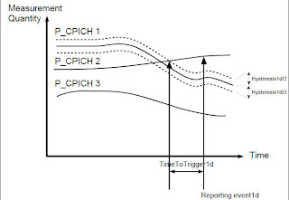 Figure 8 shows how the measured quality of P_CPICH2 becomes better than the measured quality of the best cell in the Active Set, that is P_CPICH1.Figure 8 Reporting Event 1d Concept
Event 1d handling by RNC
When a MEASUREMENT REPORT message is received at the SRNC from the UE, and the MEASUREMENT REPORT has been triggered on event 1d, Soft/Softer Handover evaluation algorithm processes the report and evaluates if the proposed candidate can be added to or replaced into the Active Set. Note that this sequence does not apply to the 1d HS event used for triggering a serving HS cell change.
Soft/Softer Handover Evaluation retains the unique cell in the event results section of the MEASUREMENT REPORT.
If the retained cell already belong to the Active Set, then Soft/Softer Handover Evaluation updates the ordered Active Set list with the quality (Ec/No) measure reported in the section Measured Results of the received report, and the evaluation process terminates with no other actions.
Soft/Softer Handover Evaluation checks if the retained cell is valid. That means that it checks if the reported cell belongs to the IAF Neighbor Subset, in other words, the cell is valid if it belongs to the IAF Monitored Subset or to the IAF Unmonitored Subset.
Retained cell is invalid
The sequence is terminated with no other actions.
Retained cell is valid but missing synchronization information
If the retained cell is a valid cell and the Cell Synchronization information is missing from the MEASUREMENT REPORT the evaluation process terminates with no other actions. The reason is that the cell synchronization information is needed to for Soft handover Execution.
Retained cell is valid
If the cell synchronization is available for the retained cell and the algorithm has not exited by one of the previous causes the evaluation proceeds.
- If the retained valid cell is not in the Active Set, and the number of cells in the Active Set ( PresActiveSet ) is lower than maxActiveSet parameter, it means that there is room for more cells in the Active Set. Soft/Softer Handover Evaluation creates a proposed Active Set by adding the retained valid cell to the Active Set.
- If the number of cells in the Active Set ( PresActiveSet ) is equal to the maximum value permitted, that is, equal to maxActiveSet, and the retained valid cell is better than the worst cell in the Active Set, then Soft/Softer Handover Evaluation creates a proposed Active Set by replacing the worst cell in the Active Set with the retained cell.
Soft/Softer Handover Evaluation then updates the ordered Active Set list with the quality (Ec/No) measure reported in the section Measured Results of the received report.
If the new proposal is accepted by Soft/Softer Handover Execution, SRNC sends the Active Set UPDATE message to the UE informing about the new Active Set and Soft/Softer Handover Evaluation updates the ordered Active Set list with the quality (Ec/No) measure reported in the section Measured Results of the received report, and the evaluation process terminates for that particular MEASUREMENT REPORT.
Note that many (most) event 1d reports will happen when a cell already in the Active Set becomes better than the best cell in the Active Set. These reports will not lead to any proposed Active Set. The ordered Active Set list is updated with the quality (Ec/No) measure reported in the section Measured Results of the received report, and the evaluation process terminates with no other actions.
4.2.7 Buffering and Queuing
There are three separate buffers for event 1x measurement reports namely the 1a/1cReporting buffer, the 1bReporting buffer, and the 1dReporting buffer.
The 1a/1cReporting buffer is used to buffer reports triggered on event 1a and event 1c and also the event-triggered periodic reports with these event identities. The buffer only holds the last received report, so a new received report overwrites a report already in the buffer.
The 1bReporting buffer is used to buffer reports triggered on event 1b. The buffer shall hold all the received reports (limited to 10). The reports are queued in order of arrival with the oldest report first and the newest report last in the queue.
The 1dReporting buffer is used to buffer reports triggered on event 1d. The buffer holds all the received reports (limited to 10). The reports are queued in order of arrival with the oldest report first and the newest report last in the queue.
If the 1bReporting buffer or the 1dReporting buffer is full when an event 1b report or an event 1d report is received, an indication is forwarded to Soft/Softer Handover Execution that the connection must be released.
When Soft/Softer Handover Evaluation is ready to process a new report, the buffers are searched in the following order, this is the priority search:
- 1dReporting buffer
- 1a/1cReporting buffer
- 1bReporting buffer
4.3 Soft and Softer Handover Execution
Once the evaluation done by the Soft/Softer Handover Evaluation algorithm has lead to a proposed Active Set the Soft/Softer Handover execution part starts. The result is one of the following:
- Radio Link addition
- Radio Link removal
- Combined Radio Link addition and Radio Link removal
- New proposal rejection, actual Active Set is maintained
- Connection is released
There is no interruption of the dataflow during Soft/Softer Handover; at least one radio link always remains active. Unlike hard handover, there is no information loss when adding/removing radio links in Soft/Softer Handover.
Soft/Softer Handover Execution makes an attempt to allocate and/or deallocate resources according to the proposal received from the Soft/Softer Handover Evaluation algorithm. If the attempt succeeds, the actions necessary to fulfill the proposal are executed. If execution fails, exception handling is performed to get back to a stable situation. If an unrecoverable error occurred during the execution, release of the connection is initiated and the function is stopped. Handover algorithms are updated with the output result from execution function. If the connection cannot be kept, release of the connection is initiated.
Soft/Softer Handover can only be performed for connections in CELL_DCH state. Thus if the UE has a connection towards a Circuit-Switched service, or has a connection to a Packed-Switched service, the connection will get the benefit of Soft/Softer Handover provided it is on CELL_DCH state.
Soft/Softer Handover Execution interacts with Capacity Management algorithms, see Capacity Management. Soft/Softer Handover Execution requests admission before adding radio links and also informs Capacity Management algorithms about successful changes in the Active Set. After Handover Execution asked Capacity Management algorithms an answer is back informing if enough resources are available for the radio link addition. Resources such as channelization codes, power, etc. are considered in this step. The resources are evaluated for the target cell.
Interaction with Capacity management
If an RL setup is denied by admission control, the UE will normally repeat the 1a or 1c eventreports. Capacity Management might perform soft congestion actions in the target cell and/or switch down the current connection to a lower rate, so that a repeated RL add requests might be admitted.
4.3.1 Soft/Softer Handover Scenarios
Soft/Softer Handover Execution can handle several different cases, depending if the connection involves just one RNC, that is, the SRNC, or the connection involves more than one RNC, SRNC/DRNC scenario.
The Figure 9 shows different examples of UE connections and the corresponding signaling.
- If no DRNC is involved the SRNC signals directly to the RBS (1).
- If DRNC(s) are involved the SRNC sends the message to the DRNC (4) and the DRNC distributes the message to RBS (5 or 6)..
- The RBS then distributes the message in all cells in the Radio Link Set (2,3 or 7, or 8,9)

Representing the softer handover part of the connection, the links of a Radio Link Set are controlled by one RBS. As an example assume that the UE has three cells in its Active Set, that is, three radio links. One of them controlled by RBS_A, the other two radio links (RL2, RL3) are controlled by RBS_B. Then RL2 and RL3 are considered in Softer Handover and they form a Radio Link Set. Both, RL2 and RL3, are in Soft Handover with RL1. In a case like this, it is said that the connection is in Soft and Softer Handover.Figure 9 SRNC/DRNC Concept
The Table 3 summarizes the different soft/softer handover scenarios:
Table 3 Soft/Softer Handover scenarios # Scenario Description 1 Intra RNC Radio Link Set Addition-Soft Handover Adding the first RL between a UE and a new RBS in the SRNC. 2 Intra RNC Radio Link Set Removal-Soft Handover Removing the last RL between a UE and an RBS in the SRNC. 3 Intra RNC Radio Link Addition-Softer Handover Adding another RL between a UE and an RBS in the SRNC. 4 Intra RNC Radio Link Removal-Softer Handover Removing one of the RLs (but not the last) between a UE and an RBS in the SRNC. 5 Inter RNC Radio Link Set Addition-Soft Handover (Iur connection not previously set up) Adding the first RL between a UE and an RBS, not yet involved, in a new DRNC. The Iur connection has not yet been established. 6 Inter RNC Radio Link Set Addition-Soft Handover (Iur connection already set up) Adding the first RL between a UE and an RBS, not yet involved, in the DRNC. The Iur has been already established. 7 Inter RNC Radio Link Set Removal-Soft Handover (Iur connection not released) Removing the last RL between a UE and an RBS in the DRNC. Connection between SRNC and DRNC remains. 8 Inter RNC Radio Link Set Removal- Soft Handover (Iur connection released) Removing the last RL between a UE and the last RBS in the DRNC. The Iur connection between the SRNC and the DRNC is released. 9 Inter RNC Radio Link Addition-Softer Handover Adding one RL between a UE and an RBS, already involved, in the DRNC. 10 Inter RNC Radio Link Removal-Softer Removal Removing one of the RLs (but not the last) between a UE and an RBS in the DRNC. 11 Inter/Intra RNC combined Radio Link Addition and Removal Adding one RL and removing one RL in the connection towards a UE. 4.3.2 Radio Link Addition
Radio link addition is normally triggered by the event 1a, event 1c, and event 1d reports from the UE, MEASUREMENT REPORT message sent to the WCDMA RAN by UE.
During execution of addition, the Admission Control algorithm in the Serving RNC (SRNC) is asked if the new RL setup can be allowed in the cell. After access has been granted the Code Control algorithms in the SRNC allocate DL channelization code, then the Power Control algorithms in the SRNC set the initial DL transmission power, UL SIR Target, and DL power range.
The SRNC then contacts the RBS, which allocates resources, starts reception, and tries to synchronize the UE on the uplink.
The SRNC sends the Active Set UPDATE message to the UE, which allocates reception resources, synchronizes to the new radio link on the downlink. The UE responds with an Active Set UPDATE COMPLETE message. Evaluation algorithms and interacting functions are informed about the new Active Set. Figure 10 shows common RRC messages between the UE and the WCDMA RAN, for radio link addition and radio link removal.
- Note:
- Removal is not part of the Addition execution and Addition is not part of Removal execution. However, both are included in the Replacement execution.
In case of Inter-RNC Radio Link Addition, the SRNC establishes signaling connections to the Drifting RNC (DRNC) over the Iur interface. Once the Iur connection exits, RBS resources are demanded by the SRNC and if resources are available the new radio link is setup.
 Figure 10 Soft/Softer Handover Radio Link Addition and Radio Link Removal.
4.3.3 Radio Link Removal
Radio Link removal is triggered by the reception of an event 1b report from the UE. The Soft/Softer Handover Evaluation algorithm sends an Active Set proposal to the Execution part in the SRNC to remove the reported cell(s) from the Active Set of the UE.
During execution of the removal, the SRNC sends an Active Set
UPDATE message to the UE, which releases the resources for that radio link and responds with an Active Set UPDATE COMPLETE message as shown in Figure 10. RBS and SRNC resources are then released for the removed radio link. Evaluation algorithms and interacting functions are informed about the new Active Set.
In case of Inter-RNC Radio Link Removal, the DRNC stays involved in the connection provided that at least one radio link uses an RBS belonging to the DRNC. If not, the Iur connection will be released.
4.3.4 Radio link Replacement
Combined radio link addition and removal replaces one radio link with another in the Active Set. Radio link replacement is normally triggered by an event 1c report or an event 1d report from the UE.
The RBS node is contacted by the SRNC. The new RBS allocates resources, starts reception, and tries to synchronize the UE on the uplink.
During replacement execution, power is determined for the radio link to be added (as usual). The SRNC sends an Active Set UPDATE message to the UE indicating which radio link to add and which radio link to remove. The UE allocates resources for the new radio link and releases corresponding resources for the old radio link. The UE responds with an ACTIVE
SET UPDATE COMPLETE message. RBS and SRNC resources are then released for the removed radio link, and Evaluation algorithms and interacting functions are informed about the new Active Set.
4.3.5 Exception Handling
The following exception cases will cause a release of the connection:
- A Detected Set report is received where the invalid cell is more than releaseConnOffset stronger than the strongest cell in the active set..
- A failed RL add/replace attempt, where the proposed cell is more than releaseConnOffset stronger than the strongest cell in the active set..
- A Measurement Control message failure for a 1x event.
- Active set update failure, that is the UE does not respond to the Active Set UPDATE message and the timer
T-ASU expires.
5 Connection Quality Monitoring
5.1 General
The connection quality is monitored in DL based on both CPICH Ec/No and CPICH RSCP and in UL based on UE TX power. This corresponds to monitoring that the current UL and DL coverage is good. The quality is monitored separately for each using the 2d, 2f, 6d and 6b events, and RNC continually keeps track of wether the DL Ec/No, the DL Rscp or the UL coverage is good or bad. When at least one of these gets bad, an IF or GSM HO attempt will be started, and if the coverage then gets good for all then the IF or IRAT HO attempt will be aborted.
An operator configurable offset for the 2d thresholds have been introduced, that can be set separately for Ec/No and Rscp, and per UeRc state. Since different Services / RABs (represented by UeRc state) might have different DL coverage, this offset can be used to set different DL triggerpoints for different RABs, when initiating IF or IRAT coverage triggered HO. The offsets can also be used to disable or encourage IF or IRAT HO for different RABs by setting high or low values. These offset parameters are labeled serviceOffset2dEcno and serviceOffset2dRscp, and are added to the event thresholds for the events 2d, 2f, 3a and 2b.
When an IF or GSM HO attempt is started, the same measurement quantity that triggered the bad quality is used. That means that if DL Ec/No coverage gets bad then a HO attempt using 3a or 2b Ec/No measurements is started, if DL Rscp coverage or UL UE Tx power gets bad then a HO attempt using 3a or 2b Rscp measurements is started.
The total connection quality is considered bad as soon as the CPICH Ec/No level for the best cell in the Active Set goes below usedFreqThresh2dEcno+ serviceOffset2dEcno, or the CPICH Rscp level for the best cell in the Active Set goes below usedFreqThresh2dRscp+ serviceOffset2dRscp, or the UE TX power reaches maximum. This should trigger an IF or GSM HO attempt.
On the other hand, the total connection quality is considered good if all three above measurements turn out to be good, i.e the CPICH Ec/No level for the best cell in the Active Set is above usedFreqThresh2dEcno+ serviceOffset2dEcno+ usedFreqRelThresh2fEcno, and the CPICH Rscp level for the best cell in the Active Set is above usedFreqThresh2dRscp+ serviceOffset2dRscp+ usedFreqRelThresh2fRscp, and the UE TX power is below ueTxPowerThresh6b. This will stop ongoing IF or GSM measurements, and if a 3a or 2b event has not yet triggered then the HO attempt will be aborted.
The connection quality monitoring is also active while using HS-DSCH and EUL.
Either of these measurements can be disabled by parameter settings. The DL Ec/No measurement can be disabled by setting timeToTrigger2dEcno to 5000, the RSCP measurement can be disabled by setting timeToTrigger2dRscp to 5000, and the UE Tx Power measurement can be disabled by the setting the parameter txPowerConnQualMonEnabled to FALSE. The DL 2d event thresholds can be set per cell by the operator.
5.2 Decision on Handover Type
When bad connection quality is detected some further conditions are checked to evaluate if an IF or GSM HO attempt shall be made. This decision is based on parameters on RNC level, cell level, and UeRc state. A further condition is that there are IF or GSM neighbor cells defined, and that the IF or GSM monitored set is not empty.
Inter-Frequency handover is only attempted if C_IfHoAllowed is set to Allowed for the current UeRc state, and FddIfHoSupp is set to On .
Inter-RAT handover is only attempted if C_GsmHoAllowed is set to Allowed for the current UeRc state, and FddGsmHoSupp is set to On.
If both Inter-Frequency handover and Inter-RAT handover are allowed and both Inter-Frequency and Inter-RAT neighbors cells exist for the cells in the Active Set, the decision to perform Inter-Frequency or Inter-RAT handover is based on a configurable parameter, hoType, defined per cell.
For cells belonging to a DRNC, this parameter can not be read over Iur, and a setting per carrier per external RNC is used instead. Due to this limitation the handover type cannot be defined per cell in external DRNC cells, only per used carrier. This parameter is called defaultHoType and can be defined together with freqBand and uarfcnDl for each used carrier frequency in each DRNC. If it is not defined a default value of GSM_PREFERRED is used.
The initial decision for start of Inter-RAT Evaluation or Inter-frequency Evaluation is based on the following rules:
- If all cells in the Active Set have the parameter hoType (or defaultHoType) set to NONE, neither Inter-Frequency nor Inter-RAT handover will be attempted.
- If at least one cell in Active Set has hoType (or defaultHoType) set to GSM_PREFERRED and no cell has hoType (or defaultHoType) set to IFHO_PREFERRED, IRAT neighbors are defined, and IRATHO is allowed for the connection, then IRAT handover will be attempted. If the HO type evaluates to GSM_PREFERRED but IRAT handover can not be done due to for example no defined GSM neighbors, then conditions for IFHO will be checked and IFHO could be attempted instead.
- If at least one cell in Active Set have hoType (or defaultHoType) set to IFHO_PREFERRED, IF neighbors are defined, and IFHO is allowed for the connection, then Inter-Frequency handover will be attempted. If the HO type evaluates to IFHO_PREFERRED but IF handover can not be done due to for example no defined IF neighbors, then conditions for IRAT HO will be checked and IRAT HO could be attempted instead. In that case, also the Inter Frequency CNHHO can be attempted, under the condition that the cnhhoSupp is set to TRUE, and the target RNC is defined as external RNC in the source RNC.
After this initial decision on type of evaluation to start, the type of evaluation stays the same until the evaluation is stopped. The evaluation is stopped when no more neighbors exist in the monitored set for the evaluation type started, or the UeRC state does not allow the evaluation to continue (see Connection Handling) or when a MEASUREMENT REPORT message for event 2f or 6b is received by the SRNC indicating that the connection quality on the currently used frequency is good enough again in both UL and DL (see Section 5.1).
5.3 Event 2d/2f Quality Monitoring
When the UE has entered state CELL_DCH, the UE capability for Inter-Frequency and GSM HO is checked. The Inter-Frequency Handover is supported in the RNC if the corresponding parameter fddIFHOsupp is set to 'ON'; in the same way the Inter-RAT Handover is supported in the RNC if the corresponding parameter fddGsmHOsupp is set to 'ON'. The Inter-Frequency Handover support is mandatory for the UE, while the Inter-RAT Handover support is not. The condition for activating P-CPICH Quality Monitoring is consequently: ( fddIFHOsupp 'ON') or ( fddGsmHOsupp'ON' and the UE supports GSM). The same conditions applies for starting the 6d/6b measurements.
Two separate MEASUREMENT CONTROL messages with “setup” for event 2d / 2f are sent to the UE, one for the Ec/No measurement and another one for the Rscp measurement. Event 2d and event 2f are relevant only for cells in the Active Set of the current WCDMA RAN used frequency. Therefore no information on Inter-Frequency cells is needed.
The UE is configured for 2d event triggering based on thresholds usedFreqThresh2dEcno+ serviceOffset2dEcno (and usedFreqThresh2dRscp+ serviceOffset2dRscp). The UE is configured for 2f event triggering based on thresholds usedFreqThresh2dEcno+ serviceOffset2dEcno+ usedFreqRelThresh2fEcno (and usedFreqThresh2dRscp+ serviceOffset2dRscp+ usedFreqRelThresh2fRscp).
If the WCDMA quality on the current used frequency goes below the 2d Ec/No threshold minus the corresponding hysteresis, and the condition is maintained during timeToTrigger2dEcno, (or the WCDMA quality on the current used frequency goes below the 2d Rscp threshold minus the corresponding hysteresis, and the condition is maintained during timeToTrigger2dRscp) then event 2d occurs, and Inter-Frequency or GSM measurements need to be performed by UE.
If the WCDMA quality on the current used frequency goes above the 2f Ec/No threshold plus the corresponding hysteresis, and the condition is maintained during timeToTrigger2fEcno, (and the WCDMA RAN quality on the current used frequency goes above the 2f Rscp threshold plus the corresponding hysteresis, and the condition is maintained during timeToTrigger2fRscp) then event 2f occurs and the UE is informed to stop IF or IRAT measurements. Note that all monitored quantities of the connection must be good before IF or IRAT measurements are stopped.
If the value of 2d threshold changes as a result of an Active Set update, for either the Ec/No or the Rscp measurement, due to different settings of the cell parameter usedFreqThresh2dEcno or usedFreqThresh2dRscp, the corresponding measurements using event 2d and event 2f must be modified with new thresholds for both events, computed according to the above description. This is also valid if the serviceOffset2dEcno or the serviceOffset2dRscp changes as a result of a change of UeRc state.
- Note:
- Ranges of absolute thresholds The absolute threshold values for the events 2d and 2f (based on the parameters and offsets described above) sent out to the UE in the MEASUREMENT CONTROL message, will be altered to conform to 3GPP ranges (i.e. -24..0 [dB] for EcNo and -115..-25 [dBm] for RSCP).
Event 2d Handling
When SRNC receives a MEASUREMENT REPORT message for event 2d from the UE, measurements for IRAT HO event 3a or IF HO event 2b is setup in the UE depending on how the parameter hoType / defaultHoType is set for the cells in the Active Set, see Section 5.2. The measurement quantity for IRAT HO event 3a or IF HO event 2b, is set automatically depending on which part of the connection quality that is bad (CPICH Ec/No or CPICH RSCP) when the measurement is started.

Figure 11 shows that the measured quality of WCDMA RAN is below the used 2d threshold - hysteresis2d/2. And if this condition remains true for a time at least timeToTrigger2dEcno, event 2d occurs. For more details on hysteresis concept, see Section 3.4.Figure 11 Reporting Events 2d and 2f Concept
Event 2f Handling
When SRNC receives a MEASUREMENT REPORT message for event 2f from the UE, measurements for IRAT HO event 3a or IF HO event 2b and associated compressed mode usage is stopped. Note that the connection quality must be good for all monitored measurements before the HO attempt is stopped.
Figure 11 shows that the measured quality of WCDMA RAN is now above the used 2f threshold plus half the value of event 2f hysteresis, if this condition remains for a time no less than timeToTrigger2fEcno then event 2f occurs. For more details on hysteresis , see Section 3.4.
5.4 UE Tx Power Monitoring (Event 6d/6b)
The Ue Tx power monitoring using events 6d and 6b is started on the same conditions as the 2d/2f events, see above. A MEASUREMENT CONTROL message with “setup” for event 6d and event 6b is prepared and sent to the UE. Event 6d and event 6b is relevant only for the Active Set of the current WCDMA RAN used frequency.
The UE is configured for event trigger decision based on the threshold ueTxPowerThresh6b, event 6d does not need a specific threshold. If the UE Tx Power reaches maximum and the condition is maintained during timeTrigg6d, then event 6d occurs and Inter-Frequency or GSM measurements need to be performed by UE. The measurement quantity for IRAT HO event 3a or IF HO event 2b, is set automatically to CPICH RSCP, and the additional relative threshold utranRelThreshRscp is also used (see Section 6.2 and Section 7.2). If the UE Tx Power goes below ueTxPowerThresh6b threshold, and the condition is maintained during timeTrigg6b , then event 6b occurs and the UE is informed to stop measurements on Inter-Frequency GSM cells.
No MEASUREMENT CONTROL message with the IE MEASUREMENT COMMAND set to ’Modify’ for event 6d and event 6b will be sent to the UE after an Active Set update. The reason is that these measurements are not based on Active Set cells or Monitored Set cells.
Event 6d Handling
When the UE Tx power reaches maximum during a time at least equal to timeTrigg6d, event 6d occurs. Note that there is no support for hysteresis for event 6d triggering, and that no threshold is used. The UE sends a MEASUREMENT REPORT message for event 6d to the SRNC. When SRNC receives the MEASUREMENT REPORT message for event 6d from the UE, measurements for IRAT HO event 3a or IF HO event 2b is set up in the UE depending on how the parameter hoType / defaultHoType is set for the cells in the Active Set, see Section 5.2. The measurement quantity is set automatically to CPICH RSCP. The additional relative threshold utranRelThreshRscp is also used.
Event 6b Handling
When the UE Tx power is below the absolute threshold ueTxPowerThresh6b during a time at least equal to timeTrigg6b, event 6b occurs. Note that there is no support for hysteresis for event 6b triggering. The UE sends a MEASUREMENT REPORT message for event 6b to the SRNC. When SRNC receives the MEASUREMENT REPORT message for event 6b from the UE, ongoing HO attempts are stopped if the DL quality for both Ec/No and Rscp is also good.
6 IRAT HO
6.1 General
The Inter-RAT Handover Evaluation algorithm performs the Inter-RAT (WCDMA RAN to GSM) handover evaluation based on the UE GSM measurement reports. At event reports, a GSM cell is proposed to make handover to, based on the reported measurements.
The Inter-RAT Handover and Cell Change provide the ability to maintain connection with a UE when moving to other radio access systems and WCDMA RAN. Inter-RAT Handover is used when the UE is using a Circuit-Switched service and is moving out from WCDMA RAN coverage area to a GSM coverage area and vice versa. Inter-RAT Cell Change is used when the UE is using a Packet-Switched service.
Inter-RAT Handover for CS services is a type of hard handover where the UE is ordered by the network to tune to another RAT, establish contact with it and then continue the traffic using resources from the new contacted system. This means that there will be small interruptions in the data flow to and from the UE. The CN and the GSM network might also assign a new speech rate to the connection, if the current rate and codec that is used in WCDMA is not supported on the GSM side.
Inter-RAT Cell Change is similar to Inter-RAT Handover. Inter-RAT Cell Change is also used when the UE is in connected mode. The major difference between Inter-RAT Handover and Inter-RAT Cell Change is that in the Inter-RAT Cell Change case there are no resources reserved in the target cell before the Inter-RAT Cell Change is executed. If the Inter-RAT Cell Change is evaluated and executed by the UE in Idle mode or connected mode on common channels it is denoted Cell Reselection or Inter-RAT Cell Reselection, see Idle Mode and Common Channel Behavior for more details.
6.2 Configuring the UE for Evaluation (3a Event)
When the UE reports event 2d or event 6d to the SRNC, the SRNC prepares setup for event 3a if measurements for support of Inter-RAT handover shall be started. See Section 5.2. A MEASUREMENT CONTROL message with “setup” for event 3a is sent to the UE.
The UE is configured with the GSM Monitored Subset, built from GSM neighbor cells of the Active Set cells.
If the UE requires Compressed Mode Control for measuring on the GSM frequencies, the UE is configured to use specific transmission gap pattern sequences. Measurement Handling algorithm and the Compressed Mode function, both on the SRNC, will take care of compressed mode configuration.
The UE is configured to report according to usedFreqThresh2dEcno+ serviceOffset2dEcno+ utranRelThresh3aEcno and gsmThresh3a parameters (in the case when bad connection quality has been triggered for CPICH Ec/No). In the case when bad connection quality has been triggered for CPICH RSCP, the UE is configured taccording to usedFreqThresh2dRscp+ serviceOffset2dRscp+ utranRelThresh3aRscp and gsmThresh3a parameters. When bad connection quality has been triggered in UL for UE TX power (event 6d), the UE is configured according to usedFreqThresh2dRscp+ serviceOffset2dRscp+ utranRelThresh3aRscp+ utranRelThreshRscp and gsmThresh3a parameters, see Event 3a.
Ongoing IRAT measurements might need to be modified as a result of an Active Set update. If the GSM monitored set is changed, the new GSM monitored set must be sent to the Ue, i.e. a change of GSM neighbors.
When the UE is measuring already on Inter-RAT Handover, the evaluation is stopped in case of:
- the UeRC state does not allow the evaluation to continue (e.g. due to rate connection switching, see Connection Handling), or
- the GSM Monitored Set becomes empty at Active Set update, or
- the connection quality becomes good, i.e. if an event 2f or event 6b or both occur before event 3a occurs.
- Note:
- Ranges of absolute thresholds for event 3a The absolute threshold values for the events 3a (based on the sum of absolute threshold values for event 2d and relative threshold values for event 3a) sent out to the UE in the MEASUREMENT CONTROL message, will be altered to conform to 3GPP ranges (i.e. -24..0 [dB] for EcNo and -115..-25 [dBm] for RSCP).
Service Based GSM HO
The event 3a, triggered with a modified UTRAN threshold, is used when a connection is a candidate for Service Based Handover feature. This threshold (defined for RAB “Speech only”) by default does not take into account any UTRAN quality issues and limits the report of the event 3a, to the triggering condition of the GSM target cell.
The triggering is performed when the estimated quality of the WCDMA RAN used frequency is below the threshold C_utranThresh3aForcedGsm and the measured GSM carrier RSSI of a GSM cell is above the absolute threshold gsmThresh3a, during a time at least equal to TimeToTrigger3a.
The condition related to the WCDMA RAN used frequency is always satisfied, by setting C_utranThresh3aForcedGsm (defined only for P-CPICH Ec/No quantity measurement) to the highest possible value (e.g 0 [dB]). Note that the constant is not defined for CPICH RSCP, since the only purpose of C_utranThresh3aForcedGsm is to make the UTRAN cell condition always fulfilled.
6.3 Inter-RAT Handover Evaluation
6.3.1 General
As soon as the connection quality becomes bad (see Section 5.1), measurements on the GSM cells (Inter-RAT frequency measurements) can be activated. When the measurements start, the connection quality is checked to determine which part of the WCDMA RAN connection quality is bad. The check is done in the following priority order: first downlink CPICH Ec/No, then downlink CPICH RSCP, then uplink Ue TX power. The measurement quantity is then set automatically depending on the check result. The measured Inter-RAT neighbors are decided by the Measurement Handling algorithm.
The Inter-Rat Handover Evaluation is disabled after the MEASUREMENT CONTROL message that terminates GSM measurements is sent from SRNC to the UE. The message is prepared by the Measurement Handling algorithm.
If the Inter-Rat Handover Evaluation receives an event 3a MEASUREMENT REPORT while it is already processing another MEASUREMENT REPORT, the new one is buffered. There is one buffer for the only specified event 3a MEASUREMENT REPORT namely the 3aReporting buffer for event 3a. The buffer holds only the last received report so a new received report overwrites a report already in the buffer.
6.3.2 Event 3a handling by RNC
When the Inter-Rat Handover Evaluation algorithm receives a MEASUREMENT REPORT message for event 3a, the following actions are taken.
Order the GSM cells in the measurement report according to their GSM quality measure and keep them in a list. When doing this ordering, discard all cells whose GSM quality measure according to gsmMeasQuant3 (GSM Carrier RSSI) is below gsmThresh3a, and discard all cells that are not BSIC verified.
Keep the GSM cell with the best quality measure (the first cell in the ordered GSM list) as the cell to propose handover to. Start a GSM HO attempt to this cell, and start the timer gsmhoPropRepeatInterval.
If the IRATHO proposal was successful, then stop the sequence.
If the proposal was a failure then check the event1a,1c,1d eventbuffers for soft/softer HO. If there are any waiting reports, handle them according to SHO_Eval algorithm and wait for confirmation. Then return here.
If the IRATHO proposal was rejected and if an event 3a report is buffered, then terminate the sequence (and process that report).
If the proposal was rejected with cause "Relocation Preparation Failure" or with cause "Handover/CellChange from Utran Failure" and if no event 3a is buffered, then the GSM HO attempts shall be repeated. The number of repeated attempts, not including the first attempt, is set by the parameter gsmHoAmountPropRepeat. The time interval between the attempts is set by parameter gsmHoPropRepeatInterval. After a failed IRATHO attempt, the event1a,1c,1d eventbuffers for soft/softer HO shall be checked, and received event shall be processed before any repeated GSM HO attempts. If there are more than one GSM cell retained in the 3a measurement report, the repeated attempts shall be made for these cells in quality order. If failed attempts have been made for all cells in the measurement report without reaching gsmHoAmountPropRepeat re-attempts, the cell(s) in the 3a report shall be attempted again in quality order.
If the proposal was rejected with cause "Other" and if no event 3a report is buffered, then terminate the sequence.
Event 3a
The event 3a occurs according to below:
- in case of the connection quality has been triggered for CPICH Ec/No, event 3a is triggered when the estimated quality of the WCDMA RAN used frequency is below the threshold usedFreqThresh2dEcno+ serviceOffset2dEcno+ utranRelThresh3aEcno and the measured GSM carrier RSSI of a GSM cell is above the absolute threshold gsmThresh3a, during a time at least equal to timeToTrigger3a;
- in case of the connection quality has been triggered for CPICH RSCP, the event 3a is triggered when the estimated quality of the WCDMA RAN used frequency is below the threshold usedFreqThresh2dRscp+ serviceOffset2dRscp+ utranRelThresh3aRscp and the measured GSM carrier RSSI of a GSM cell is above the absolute threshold gsmThresh3a, during a time at least equal to timeToTrigger3a;
- in case of the connection quality has been triggered in UL for UE TX power (event 6d, see Event 6d Handling), the event 3a is triggered when the estimated quality of the WCDMA RAN used frequency is below the threshold usedFreqThresh2dRscp+ serviceOffset2dRscp+ utranRelThresh3aRscp+ utranRelThreshRscp and the measured GSM carrier RSSI of a GSM cell is above the absolute threshold gsmThresh3a , during a time at least equal to timeToTrigger3a.
Note that BSIC verification is required, so GSM measured carrier RSSI must have a valid decoded BSIC according to GSM Monitored Subset.
 Figure 12 shows that the measured quality in WCDMA RAN is below the used 3a threshold, and at the same time the quality of the measured GSM frequency is above the defined threshold gsmThresh3a, and both conditions occur at the same time, and for a time not less than timeToTrigger3a, then event 3a occurs. Note that the hysteresis3a also applies.Figure 12 Reporting Event 3a Concept
6.4 Inter-RAT Handover Execution
Once the evaluation carried by the Inter-Rat Handover Evaluation algorithm has lead to a proposed GSM cell, Inter-RAT Handover Execution starts. The result of the execution part is one of the following:
- Hand over the UE connection to a GSM cell. That is, the UE is finally connected to the GSM cell and WCDMA RAN resources related to the UE connection are released.
- The UE connection remains on the WCDMA RAN due to a handover to GSM failure.
6.4.1 Services
Inter-RAT Handover function can only be executed for connections in CELL_DCH state and only for UEs connected towards a Circuit-Switched service. The Circuit-Switched service can be either voice or data. For speech different AMR speech rates might be supported in 3G and 2G systems, and the CN and the GSM system might set up a speech connection after a HO using a different rate.
6.4.2 Interaction with Other Functions
Inter-RAT Handover interacts with other ongoing functions related to the same UE connection. Once the function is enabled by the Inter-Rat Handover Evaluation, when no pending actions are affecting the UE connection, Inter-RAT Handover Execution sends the petition to the UMTS Core Network for handover to GSM.
Inter-RAT Handover Execution is dependant on that the source and target system has enough knowledge and consistent information of each other to successfully perform the Inter-RAT Handover.
6.4.3 Actions Taken by Inter-RAT Handover Function
According to Section 6.3, if the UE has reported many GSM cells, a priority is established to start trying to handover to the best GSM reported cell. The flow of the algorithm is stated in Section 6.3.2, thus more than one proposal may come to Inter-RAT Handover execution, but just one at a time.
When the proposal is received from the Inter-RAT Handover Evaluation algorithm, the execution part sends a RELOCATION REQUIRED message to the UMTS Core Network (CN) to request for handover to GSM, and the timer T_RELOC_prep is started in the SRNC. The message includes the target cell ID and information about UE capabilities and security information.
The GSM system is contacted. The GSM target system allocates resources. A RELOCATION COMMAND message is sent to SRNC. The SRNC stops the timer T_RELOC_prep.
The SRNC sends HANDOVER FROM UTRAN COMMAND message to the UE to initiate the handover. The GSM message HANDOVER COMMAND is included in the handover message. The resources on WCDMA RAN side are kept to allow the UE return to the old channels in case of handover failure.
When the target GSM BSS detects the UE and the handover is completed the UMTS Core Network initiates a IU CONNECTION RELEASE. At the reception of IU CONNECTION RELEASE with “successful relocation” indicator, the SRNC deallocates all resources related to the UE connection.
Figure 13 shows the RRC messages between the UE and the WCDMA RAN, for the Inter-RAT Handover.

Figure 13 Inter-RAT Handover Sequence6.4.4 Exception Handling
The philosophy on how to handle exceptional cases is to keep the connection if possible. In contrast to Soft/Softer Handover there is no risk of uncontrolled interference problems when the handover fails. The following cases must be considered:
If a MEASUREMENT CONTROL failure occurs for event 3a, the SRNC cancels the Inter-RAT Handover and the connection is released.
If the RELOCATION PREPARATION FAILURE message is received at SRNC from the Core Network, Inter-RAT Handover is canceled, and the connection is kept, if possible. If the cause of the message is “No resource available”, the Inter-Rat Handover Evaluation algorithm is informed that the unsuccessful allocation failed due to lack of resources in the target system. See Section 6.3.2 to see how the Inter-Rat Handover Evaluation handles the following possible GSM cells in the list.
If it is not possible to fulfill the RELOCATION COMMAND message for any reason, the function is cancelled and the RELOCATION CANCEL message is sent from the SRNC to Core Network. The connection is kept, if possible.
If the timer T_RELOC_prep expires, it means that the target GSM BSS system did not answer, the function is cancelled, and the RELOCATION CANCEL message is sent from SRNC to Core Network.
If the UE fails to access the GSM cell and returns to the old channel then a RADIO LINK RESTORE INDICATION message is sent from RBS to the SRNC to indicate that the UE has returned to the old channel. When the UE comes back to the old channel, a HANDOVER FROM UTRAN FAILURE message is sent to the SRNC by the UE. The SRNC informs the Core Network that Inter-RAT Handover has failed so GSM resources can be deallocated. The Inter-RAT Handover Execution informs the Inter-Rat Handover Evaluation algorithm that the handover has failed, so then the next GSM cell in the list, if any are available, can be used to try a new Inter-RAT Handover.
6.5 Inter-RAT Cell Change Execution
Inter-Radio Access Technology Cell Change (IRATCC) handles the Cell Change and Cell Reselection of a UE in connected state to and from a GSM system. The IRATCC handles the Cell Change and Cell Reselection when the UE is connected to a Packet-Switched service.
Once the evaluation carried by the Inter-Rat Handover Evaluation algorithm has lead to a proposed GSM cell, Inter-RAT Cell Change Execution is enabled if the UE is connected to a Packet-Switched service, and the Inter-RAT Cell Change execution part starts. The result of the execution part is one of the following:
- The UE, in CELL_DCH state, changes cell and continues connected to a Packet-Switched service in the new GSM cell.
- The UE, in CELL_FACH state, reselects cell and the UE contacts the new GSM system.
- The UE remains in the WCDMA RAN connected to a Packed-Switched service, due to Inter-RAT Cell Change failure.
Figure 14 shows a typical model for the Packet-Switched network with WCDMA RAN and GSM network.
A cell plan for such a network will initially consist of smaller WCDMA RAN “islands” within a bigger GSM network. With a cell plan like this, IRATCC function is necessary to avoid dropped Packet-Switched calls due to lack of WCDMA RAN coverage.
6.5.1 Services
Inter Radio Access Technology Cell Change is used when the UE is connected to a Packet-Switched service only. In cases where the UE is connected to both PS and CS core network, the change between the systems is handled by Inter-RAT Handover Execution.
When the UE is in the CELL_FACH state, the UE will autonomously select a new cell based on broadcasted information (also known as Cell Reselection), see Idle Mode and Common Channel Behavior. With the UE in the CELL_DCH state, the WCDMA RAN will decide when to make the Inter-RAT Cell Change to GSM based on event-triggered measurement reports from the UE. WCDMA RAN controls which measurements will be made by the UE and which events will trigger a report.
With the UE in the CELL_DCH state, IRATCC is dependent on Compressed Mode, see Section 3.6, that enables the UE to measure on a cell (in a different system) while still maintaining communication with the current system. In the CELL_FACH state, the UE receives information on how to create gaps for Inter-RAT measurements from information broadcasted on the BCCH.
An Inter-RAT Cell Change from GSM to WCDMA RAN is equal to a signaling connection and RAB establishment, but having a special cause value indicating “Inter-RAT Cell Change” or cell reselection.
6.5.2 Interactions with Other Functions
Inter-RAT Cell Change interacts with other ongoing functions related to the same UE connection. Once the IRATCC Execution is enabled by the Inter-Rat Handover Evaluation (Cell Change WCDMA RAN to GSM), when no pending actions are affecting the UE connection and the UE is in CELL_DCH state, Inter-RAT Cell Change Execution sends the CELL CHANGE ORDER FROM UTRAN message to the UE. In case the UE is in CELL_FACH state, IRATCC Execution is triggered by the reception of SRNS CONTEXT REQUEST message from the Packet-Switched Core Network, which happens just after the UE has sent the ROUTING AREA UPDATE message in the target system.
Inter-RAT Cell Change Execution is dependant on that the source and target system has enough knowledge and consistent information of each other to successfully perform the Inter-RAT Cell Change.
6.5.3 Scenarios
IRATCC handles the use scenarios listed in Table 4.
Table 4 Scenarios in Inter-RAT Cell Change # Scenario Description 1 IRATCC from UTRAN to GPRS, UE on dedicated channel. The Serving RNC orders the UE to make a Inter-RAT Cell Change to target GSM cell. A RA Update is sent in target system by the UE that triggers the CN to start SRNS context transfer from source SRNC to source SGSN 2 IRATCC from UTRAN to GPRS, UE on common channel. The UE measures, evaluates and initiates the Cell Reselection towards the target GSM cell. A RA Update is sent in target system by UE that triggers the CN to start SRNS context transfer from source SRNC to source SGSN. 3 IRATCC from GPRS to UTRAN In this case it is either the UE that decides about the Cell Reselection or the network that orders the Inter-RAT Cell Change. The UE performs a Inter-RAT Cell Change towards the WCDMA RAN target cell. When signaling connection is established an RA Update message is sent to the CN. 6.5.4 IRATCC from WCDMA RAN to GPRS, UE on Dedicated Channel
The case is initiated at reception of a MEASUREMENT REPORT message that indicates that the quality of the connection (in case of the connection quality has been triggered for P-CPICH Ec/No) is below the used 2d Ec/No threshold minus the corresponding hysteresis. The Measurement Handling algorithm prepares a list of GSM cells according to the UE home PLMNid and according to UE capability on GSM. Both measurement criteria and list of GSM cells are sent to UE. Compressed mode is started, if needed. When the UE detects that the WCDMA RAN quality is below the used 3a threshold and at the same time the measured quality on a GSM cell is above gsmThresh3a, the UE sends a MEASUREMENT REPORT for event 3a to SRNC. The Inter-Rat Handover Evaluation orders the reported GSM possible target cells. Starting by the best cell, a Inter-RAT Cell Change proposal is sent to the IRATCC execution function.
SRNC initiates the Inter-RAT Cell Change in the UE by sending the CELL CHANGE ORDER FROM UTRAN message to UE. The message includes information of the RAB to hand over and a target cell description. The UE synchronizes to GSM/GPRS and sends a ROUTING AREA UPDATE message. The next step is done by the Packet-Switched Core Network, which sends a SRNS CONTEXT REQUEST message that includes the RABid for which the context must be transferred. At this particular moment the DL transmission is stopped.
The SRNC sends an SRNS CONTEXT RESPONSE message. The Packet-Switched Core Network initiates the release of the Iu connection by sending the IU RELEASE COMMAND message. When this message is received by the SRNC, the Iu bearers are released. At this point radio resources are released. SRNC terminates the Iu release by sending a IU RELEASE COMPLETE message to the PS Core Network.
Figure 15 shows the RRC messages between the UE and the WCDMA RAN, for the IRAT Cell Change with UE on Dedicated Channel.
 Exception CasesFigure 15 Inter-RAT Cell Change Sequence
The rule of thumb when handling exceptional cases is to maintain the connection. In contrast to Soft/Softer Handover there is no risk of interference problems when the handover fails.
When the IRATCC is cancelled, ongoing execution is stopped and the Inter-Rat Handover Evaluation algorithm is informed. The Inter-Rat Handover Evaluation algorithm then decides whether measurements and compressed mode need to be terminated or not. The following cases must be considered
If the UE sends a MEASUREMENT CONTROL FAILURE message the SRNC will cancel IRATCC Execution and the connection is released.
If the UE fails to access the GSM/GPRS cell and returns to the old channel. A RADIO LINK RESTORE INDICATION is sent from RBS to the SRNC to indicate that the UE has returned to the old channel, then the UE will send a CELL CHANGE ORDER FROM UTRAN FAILURE message to the SRNC. The Inter-Rat Handover Evaluation is informed about the failure.
If there is an invalid RAB id in the SRNS CONTEXT TRANSFER, the SRNC will respond with SRNS CONTEXT RESPONSE using the indicator that “RABs Context Failed to Transfer”, due to invalid RAB id.
6.5.5 IRATCC from WCDMA RAN to GPRS, UE on Common Channel
The UE measures, evaluates, and initiates the Cell Reselection towards the target GSM/GPRS cell. A Routing Area (RA) update is sent in the target system by the UE that triggers the PS CN to start SRNS context transfer from the source SRNC to source SGSN. The SRNC acknowledges the UE decision when the message SRNS CONTEXT REQUEST is received at the SRNC. The message includes the RABid for which the context must be transferred. At this point anyway, no stop of the DL transmission is initiated. The SRNC sends an SRNS CONTEXT RESPONSE message. The following step is commanded by PS CN, which sends the IU RELEASE COMMAND message to the SRNC. Once received by SRNC, the Iu connection is released.
Exceptional Cases
If there is an invalid RAB id in the SRNS CONTEXT TRANSFER, the SRNC will respond with SRNS CONTEXT RESPONSE using the indicator that “RABs Context Failed to Transfer”, due to invalid RAB id.
6.5.6 IRATCC from GPRS to WCDMA RAN
In this case it is either the UE that decides about the Cell Reselection or the GSM network that orders the Inter-RAT Cell Change. The UE performs an Inter-RAT Cell Change towards the WCDMA RAN target cell. When the signaling connection is established, a ROUTING AREA UPDATE message is sent to the PS CN.
The case is initiated by an RRC connection establishment initiated by the UE towards the WCDMA RAN. When the UE has tuned to the WCDMA RAN cell, it will access the WCDMA RAN. The establishment cause in this case will be either “Inter-RAT Cell Change order” or “Inter-RAT Cell Reselection” depending on whether the UE was ordered by the GSM network to change system or if the UE performed a Cell Reselection. The UE will send a ROUTING AREA UPDATE message to the CN as part of the signaling connection establishment. The update is transparent to the WCDMA RAN.
If a new P-TMSI was provided to the UE in the ROUTING AREA UPDATE ACCEPT message (also transparent to WCDMA RAN and sent within the signaling connection establishment), the UE will respond with a ROUTING AREA UPDATE COMPLETE message, that is transparent to the WCDMA RAN. It is possible that signaling ends here if there is no data to send either on UL or DL. The PS CN will release the connection in that case. If the UE has user data waiting to be sent on UL, it will send a SERVICE REQUEST message to the PS CN transparently through the WCDMA RAN. RAB establishment is triggered in the WCDMA RAN by the reception of a SERVICE REQUEST message from the UE or if the CN has data to send on downlink.
7 Inter Frequency HO
7.1 General on Inter-Frequency Handover Evaluation and Execution
Inter-Frequency Handover provides the ability to maintain connection with a UE when moving between different frequencies within the WCDMA RAN when the UE is in connected mode.
The Inter-Frequency Handover Evaluation evaluates if IFHO shall be proposed. The Inter-Frequency Handover Evaluation bases its decision on P-CPICH quality measures on the currrently used frequency and on one or more non-used frequencies . If the evaluation result is positive, one cell on a non-used frequency is proposed to Inter-Frequency handover Execution.
If the evaluation done by Inter-Frequency Handover evaluation is positive, a new cell on a different frequency will be proposed. Resources on the new cell will be allocated and actions needed to fulfil the proposal is executed. If the execution fails , exception handling is performed to get back to the previous Active Set on the original frequency and continue service. If the criteria is met that the connection can not be kept, release of the connection is initiated.
Inter-Frequency Handover is a hard handover where the UE is ordered by the network to tune to another frequency. This means that there will be small interruptions in the data flow to and from the UE.
7.2 Configuring the UE for Evaluation (Event 2b)
When the UE reports event 2d or event 6d to the SRNC, the SRNC prepares setup for event 2b if measurements for support of Inter-Frequency handover shall be started see Section 5.2. A MEASUREMENT CONTROL message with “setup” for event 2b is sent to the UE.
The UE is configured with the Inter-Frequency Monitored Subset, built from Inter-Frequency neighbor cells of the Active Set cells.
If UE requires Compressed Mode Control for measuring on other frequencies, the UE is configured to use specific transmission gap pattern sequences. See Section 3.6.
In the case when bad connection quality has been triggered for CPICH Ec/No, the UE is configured to report for the used frequency, according to usedFreqThresh2dEcno+ serviceOffset2dEcno+ UsedFreqRelThresh4_2bEcno and for the unused frequency according to NonUsedFreqThresh4_2bEcno+ serviceOffset2dEcno. If bad connection quality has been triggered for CPICH RSCP, the UE is configured to report for the used frequency according to usedFreqThresh2dRscp+ serviceOffset2dRscp+ UsedFreqRelThresh4_2bRscp and for the unused frequency according to NonUsedFreqThresh4_2bRscp+ serviceOffset2dRscp. When bad connection quality has been triggered in UL for UE TX power (event 6d), the UE is configured to report for the used frequency according to usedFreqThresh2dRscp+ serviceOffset2dRscp+ UsedFreqRelThresh4_2bRscp+ utranRelThreshRscp and for the unused frequency according to NonUsedFreqThresh4_2bRscp+ serviceOffset2dRscp.
Ongoing Inter-Frequency Handover measurements might need to be modified as a result of an Active Set update. If the Inter-Frequency Monitored Set is changed, the new Inter-Frequency Monitored Set must be sent to the Ue, i.e. change of Inter-Frequency neighbors.
When the UE is measuring already on Inter-Frequency Handover , the evaluation is stopped in case of:
- the UeRC state does not allow the evaluation to continue (e.g. due to rate connection switching, see Connection Handling), or
- the Inter-Frequency Monitored Set becomes empty at Active Set update, or
- the connection quality becomes good, i.e. if an event 2f or event 6b or both occur before event 2b occurs.
- Note:
- Ranges of absolute thresholds for event 2b The absolute threshold values for the events 2b (based on the sum of absolute threshold values for event 2d and relative threshold values for event 2b) sent out to the UE in the MEASUREMENT CONTROL message, will be altered to conform to 3GPP ranges (i.e. -24..0 [dB] for EcNo and -115..-25 [dBm] for RSCP).
7.3 Inter-Frequency Handover Evaluation
7.3.1 General
The Inter-Frequency evaluation is started if IFHO neighboring cells are configured and at least one cell in the Active Set have the parameter hoType / defaultHoType set to IFHO_PREFERRED, see Section 5.2. The Inter-Frequency Handover evaluation algorithm evaluates if Inter-Frequency measurement shall be started and based on those measurements, if Inter-Frequency Handover Execution should be done.
As soon as the connection quality becomes bad (see Section 5.1), measurements on the unused frequencies (Inter-Frequency measurements) are activated. When the measurements start, the connection quality is checked to determine which part of the connection quality is bad. The check is done in the following priority order: first downlink CPICH Ec/No, then downlink CPICH RSCP, then uplink Ue TX power. The measurement quantity is then set automatically depending on the check result. The measured Inter-Frequency neighbors are decided by the Measurement Handling algorithm.
The Inter-Frequency Handover Evaluation is enabled after that the first MEASUREMENT CONTROL message that initiates IFHO measurements has been sent from SRNC to the UE. The message is prepared by Measurement handling. That is, when a MEASUREMENT REPORT for the event 2d or event 6d is received at the SRNC, IFHO measurements on unused frequency are setup and a MEASUREMENT CONTROL message with the IEF Monitored Subset and the reporting criteria is sent to the UE. From this moment the the Inter-Frequency Handover Evaluation algorithm is enabled in the SRNC and ready to evaluate measurement reports for event 2b received from the UE.
The Inter-Frequency Handover Evaluation is disabled after the MEASUREMENT CONTROL message that terminates IEF measurements is sent from SRNC to the UE. The message is prepared by the Measurement Handling algorithm.
If the Inter-Frequency Handover Evaluation receives an event 2b MEASUREMENT REPORT while it is already processing another MEASUREMENT REPORT, the new one is buffered. There is one buffer for the only specified event 2b MEASUREMENT REPORT namely the 2b Reporting buffer for event 2b. The buffer holds only the last received report so a new received report overwrites a report already in the buffer.
The event 2b is triggered based on either Ec/No or RSCP depending on what part of the connection quality that is bad, but before an IFHO is attempted it is checked that the reported IF cell on the non-used frequency fulfills the minimum quality for both Ec/No and RSCP, that is fulfills both NonUsedFreqThresh4_2bEcno and NonUsedFreqThresh4_2bRscp. This check can also be disabled by setting the parameter to it's minimum value, for either Ec/No or RSCP.
7.3.2 Event 2b handling by RNC
When the Inter-Frequency Handover Evaluation algorithm receives a MEASUREMENT REPORT message for event 2b the following actions are taken.
If the connection is using HS or EUL when a 2b report is recieved, the target cell must have the same capability, otherwise the connection is first switched to DCH/HS or DCH/DCH (to match the target cell capability) before the IFHO can be executed.
Order the cells of the non-used frequencies in Measured Results of the measurement report according to their Ec/No values and keep them in a list. If the measurement report is missing Rscp values or if nonUsedFreqThresh4_2bRscp = -115 then Rscp values shall not be used or checked. If nonUsedFreqThresh4_2bEcno = -24 then Ec/No values shall not be checked. Otherwise check the values and discard the report if Ec/No < nonUsedFreqThresh4_2bEcno or Rscp < nonUsedFreqThresh4_2bRscp.
Retrieve the first cell in the ordered non-used frequencies cell list i.e. the best non-used frequency cell. Start an IFHO attempt to this cell and start the timer IfhoPropRepeatInterval.
If the IFHO proposal lead to a successful IFHO, then clear all report buffers and Terminate the sequence.
If the attempt fails then check the event1x eventbuffers for soft/softer HO. If there are any waiting reports, handle them according to SHO_Eval algorithm and wait for confirmation. Then return here.
If an event 2b report is buffered, then terminate the sequence (and process that report)
If no event 2b report is buffered, then IFHO attempts shall be repeated. The number of repeated attempts, not including the first attempt, is set by the parameter IfhoAmountPropRepeat. The time interval between the attempts is set by parameter IfhoPropRepeatInterval. After a failed IFHO attempt, the event1x eventbuffers for soft/softer HO shall be checked, and a received event shall be processed before any repeated IFHO attempts. If there are more than one IF cell retained in the 2b measurement report, the repeated attempts shall be made for these cells in quality order. If failed attempts have been made for all cells in the measurement report without reaching IfhoAmountPropRepeat re-attempts, the cell(s) in the 2b report shall be attempted again in quality order.
7.4 Inter-Frequency Handover Execution
Once the evaluation carried out by Inter-Frequency Handover Evaluation has lead to a proposed target WCDMA RAN cell, Inter-Frequency Handover is enabled, and the Inter-Frequency Handover Execution part starts. The result of the execution part is one of the following:
- Handover the UE connection to a new WCDMA RAN frequency succeeds. Resources related to the old Active Set are released.
- The UE connection remains on the old Active Set on the source frequency due to a handover failure.
Regardless of the number of radio links included in the old Active Set, the connection is always set up on only one radio link on the new frequency.
7.4.1 Services
Inter-Freqency Handover function can be executed for all CS and PS connections. For speech AMR calls the same rate and codec are kept.
7.4.2 Interactions with Other Functions
Inter-Frequency Handover interacts with Capacity Management, see Capacity Management. The purpose of Capacity Management is to maximize the capacity in the WCDMA RAN while maintaining the requested Quality of Service and coverage. Inter-Frequency Handover requests admission before handing over to the radio link in the target cell.
Inter-Frequency Handover interacts with other functions related to the same UE connection. Once the function is enabled by the Inter-Frequency Handover Evaluation, when no pending actions are affecting the UE connection, the handover is executed.
7.4.3 Scenarios
Inter-Frequency Handover Execution can handle several different cases, depending if the connection involves just one RNC, that is, the SRNC, or the connection involves more than one RNC, SRNC/DRNC scenario.
Table 5 Scenarios in Inter-Frequency Handover # Scenario Description 1 Intra-RNC, target RBS not yet involved. Timing-reinitialised, Inter-Frequency handover to a cell served by an RBS controlled by the SRNC. That RBS is not involved in the Active Set of the UE on the source frequency. 2 Intra-RNC, target RBS already involved. Timing-reinitialised Inter-Frequency handover to a cell served by an RBS controlled by the SRNC. That RBS is involved in the Active Set of the UE on the source frequency. 3 Inter-RNC, target RBS already involved. Timing-reinitialised Inter-Frequency handover to a cell served by an RBS controlled by a DRNC. That RBS is involved in the Active Set of the UE on the source frequency. 4 Inter-RNC, SCCP connection not set up. Timing-reinitialised Inter-Frequency handover to a cell served by an RBS controlled by a DRNC. No SCCP connection is established between the SRNC and the DRNC for that UE. 5 Inter-RNC, target RBS not yet involved, SCCP connection set up. Timing-reinitialised Inter-Frequency handover to a cell served by an RBS controlled by a DRNC. That RBS is not involved in the Active Set of the UE on the source frequency, but another RBS controlled by the DRNC was, so an SCCP connection is established between the SRNC and the DRNC for that UE. 7.4.4 Actions taken by the Inter-Frequency Handover Function.
According to Section 7.3, if the UE has reported many Inter-Frequency cells, a priority is established to start trying handover to the best Inter-Frequency cell. The flow of the algorithm is stated in Section 7.3.2, thus more than one proposal can come to Inter-Frequency Handover execution, but just one at a time.
Figure 16 shows the RRC messages between the UE and the WCDMA RAN, for Inter-Frequency Handover.
 If the targeted cell is owned by the SRNC, the Admission Control Algorithm in the SRNC decides if the new radio link setup/Addition can be allowed in the cell. If granted, the Code Control algorithms in the SRNC allocate DL channelization code. If the targeted cell is owned by a DRNC, the SRNC will send the radio link setup/addition to the DRNC. The Admission Control Algorithm in the DRNC decides if the new radio link setup/addition can be allowed in the cell. If granted, the Code Control algorithms in the DRNC allocate DL channelization code. Further Power Control algorithms in the SRNC set the initial DL transmission power, UL SIR Target and DL power range (maximum DL power and minimum DL power).Figure 16 Inter-Frequency Handover Sequence
The new RBS is contacted by the SRNC/DRNC. The new RBS allocates resources, starts reception and tries to synchronize the UE on the uplink.
The SRNC sends PHYSICAL CHANNEL RECONFIGURATION message to the UE, which synchronizes to the new radio link on the downlink. The UE responds with PHYSICAL CHANNEL RECONFIGURATION COMPLETE when synchronization has been obtained. The radio links of the old Active Set are released and the Evaluation algorithms and interacting functions are informed about the new Active Set.
A MEASUREMENT CONTROL message is sent to the UE indicating a new set of intra frequency neighbors.
A MEASUREMENT CONTROL message is sent to the UE ordering the UE to stop measurements for event 2b.
7.4.5 Exception Handling
The rule of thumb when handling exceptional cases is to maintain the connection. The following cases are considered:
- If the UE fails to access the target cell and returns to the old Active Set the a PHYSICAL CHANNEL RECONFIGURATION FAILURE message with failure cause Physical Channel failure is sent from the UE to the SRNC to indicate that the UE has failed to synchronize on the target cell and returned to the source (old) channel. The function informs the Inter-Frequency Handover Evaluation algorithm that the handover has failed, so that a new evaluation can be performed.
- If allocation of resources in the target cell is not granted, the Inter-Frequency handover is aborted and the Inter-Frequency Handover Evaluation is informed that the handover failed, so that a new evaluation can be performed.
8 HSDPA
When the UE moves between cells, the HSDPA connection is maintained by means of intra-frequency serving HS-DSCH Cell Change between the AS cells. The Cell Change evaluation is triggered only if the parameter hsCellChangeAllowed is set to TRUE. The serving cell change is normally triggered by event 1d HS, that is a change of the best cell within the Active set, but a serving cell change can also be triggered when the current serving cell should be removed from the Active set.
If Enhanced Uplink is supported in the network the Serving EUL cell is always the same as the Serving HS-DSCH cell, and the Cell Change is performed for both EUL and HSDPA at the same time.
8.1 Measurements for HSDPA Mobility Handling
The purpose of Measurement Handling for the HSDPA is to collect, control and store the UE measurements needed to the HSDPA mobility handling and to distribute these to the involved HSDPA mobility procedures, as illustrated in Figure 17.

Figure 17 Mobility entities involved in the HSDPA mobility procedures.Event 1d HS for Serving HS-DSCH (and EUL) Cell Change
When PS Interactive using either DCH or HSDPA is started, an extra MEASUREMENT CONTROL related only to the event 1d HS , is sent to the UE having another MEASUREMENT ID than the MEASUREMENT CONTROL message dealing with the conventional event 1d for Soft Handover evaluation. The reason for having a separate event 1d HS is to be able to get UE reports triggered by only Active Set cells and to be able to use different hysteresis and time to trigger parameters to trigger serving HS-DSCH and EUL Cell Change. It is also possible to use a different quality criteria than used for the conventional event 1d. The default quality criteria used for the event 1d HS is CPICH RSCP.
When a cell in the Active Set becomes stronger than the best cell+ hsHysteresis1d /2 in the Active Set, during a time at least equal to hsTimeToTrigger1d, event 1d HS occurs. The UE sends a MEASUREMENT REPORT message for event 1d HS to the SRNC.
When Event 1d HS is received it triggers an attempt to perform a serving HSDPA cell change to the new best cell
8.2 HS-DSCH Mobility
The combined functionality of HSDPA Mobility phase 1 and phase 2 is described below. It can be divided into the following parts:
- Serving HS-DSCH Cell Change triggered by change of “Best Cell” within the Active Set.
- Serving HS-DSCH Cell Change triggered by removal of the serving HS-DSCH cell from the Active Set.
- Coverage triggered IF or IRAT HO attempts, (controlled by a separate Licence).
- HS-DSCH Cell Selection. This can be triggered at RAB establishment or by activity, (throughput measurement).
8.2.1 Iur support
HSDPA and soft/softer HO for A-DCH is also supported over Iur. It is possible to perform a serving HS-DSCH Cell Change to or between external DRNC cells, and to perform upswitches from DCH to HSDPA over Iur. The DRNC cells must be HSDPA capable and correctly configured in the DRNC, and the following related SRNC parameters must be configured, both for the Iurlink and for External Utran cells:
ExternalUtranCell parameter cellCapability, hsdschSupport = On
Iurlink parameter cellCapabilityControl, set per DRNC, hsdschSupport = On
Iurlink parameter hspaPathlossThreshold applies for cell selection for DRNC cells
RNC parameter hsToDchTrigger, changeOfBestCellInterRnc applies for reconfigurations to DCH for DRNC cells
Note that for external DRNC cells over Iur, both a coverage relatation and a neighbour relation must be defined to support Cell Selection.
8.2.2 HS-DSCH Cell Change
The HS-DSCH Cell Change procedures will try to keep the best cell in the active set as the HS-DSCH serving cell. CPICH quality measurements for all active set cells are used to determine which cell is the best cell and trigger a serving Cell Change, that is event 1d HS. A Cell Change can also be triggered if Soft/Softer Handover removes the current serving cell from the active set. A serving HS-DSCH Cell Change can only be performed to a “Suitable HS-DSCH cell”, which means a cell in the active set that supports HSDPA. The UE measurement quantity used to define the best cell is controlled by the parameter hsQualityEstimate, and hysteresis and time to trigger values can also be set separately for the event 1d HS. This means that Cell Change triggered by change of best cell can be tuned without affecting soft/softer HO. If a serving HS-DSCH Cell Change attempt fails, a fallback to DCH is normally attempted instead.
When a serving HS-DSCH Cell Change is triggered by change of best cell, that is event 1d HS, then RNC will take the following steps:
- If the parameter hsCellChangeAllowed is TRUE, a valid target cell evaluation is performed within the current active set. If the parameter hsCellChangeAllowed is FALSE then continue at step 4 below.
- RNC then selects the best of the active set cells that supports HS-DSCH. It has to be a HS-DSCH capable and enabled cell, and it must be better than the current serving cell by hsHysteresis1d/2. If the target cell is a DRNC cell over Iur then hsdschSupport must be set to On for the Iurlink cellCapabilityControl parameter. If these conditions are fulfilled then a Suitable HS cell is found.
- If a Suitable HS cell is found then RNC will start the serving HS-DSCH Cell Change execution. If the NBAP radio link reconfiguration (release of the HS-PDSCH resources on the old Serving HS-DSCH radio Link and setup of the HS-PDSCH resources on the new Serving HS-DSCH Radio Link) is successful, a RRC physical channel reconfiguration is performed. Finally the old HS-PDSCH resources are released and the sequence stops.
- If the Cell Change cannot be done, that is if the parameter hsCellChangeAllowed is FALSE, or if no Suitable HS cell is found, or if the Cell Change execution fails and the connection does not drop, then RNC will attempt to reconfigure to DCH instead. The reconfiguration to DCH also requires HS mob 2 licence.
- RNC then checks the parameter hsToDchTrigger and if the transition to DCH is allowed for the case “changeOfBestCellIntraRnc”. This parameter can be set to ON or OFF separately for different cases that can trigger transitions to DCH. If this transition to DCH is allowed then continue, otherwise RNC will take no more actions. If the active set contains any cells over Iur, then the case “changeOfBestCellInterRnc” instead applies for hsToDchTrigger.
- Attempt a downswitch to DCH, to a connection not using HS-DSCH. Also refer to Channel Switching. If the transition to DCH is blocked by Admission Control or fails then RNC will take no more actions.
- If the parameter hsCellChangeAllowed is TRUE, a valid target cell evaluation is performed within the current active set. If hsCellChangeAllowed is FALSE then continue at step 4 below.
- RNC then selects the best of the other remaining active set cells that supports HS-DSCH. It has to be a HS-DSCH capable and enabled cell and it must be better than the current serving cell by hsHysteresis1d/2. If the target cell is a DRNC cell over Iur then hsdschSupport must be set to On for the Iurlink cellCapabilityControl parameter. If these conditions are fulfilled then a Suitable HS cell is found.
- If a Suitable HS cell is found then RNC will start the serving HS-DSCH Cell Change execution.
- If the Cell Change cannot be done or is not allowed, that is no Suitable HS cell is found, or if hsCellChangeAllowed is FALSE or if the Cell Change execution fails and the connection does not drop, then RNC will attempt to reconfigure to DCH instead. The reconfiguration to DCH also requires HS mob 2 licence.
- Check the parameter hsToDchTrigger and if the transition to DCH is allowed for the case “servHsChangeInterRnc” or “servHsChangeIntraRnc”. The first case applies when the best cell is an external cell in another RNC, the second case applies when the best cell is an intra-RNC cell. This parameter can be set to ON or OFF separately for different cases that can trigger transitions to DCH. If the transition to DCH is not allowed then RNC shall release the connection. For the case when the best cell is an external cell the UE is asked to reestablish the connection in the DRNC, and the release cause Direct Signalling Connection Re-Establishment is used ( DSCR ). The PDP context is also kept to enable a faster reconnection.
- Attempt a downswitch to DCH, to a connection not using HS-DSCH. Also refer to Channel Switching. If the transition to DCH is blocked by Admission Control or fails then the connection shall be released.
8.2.3 Coverage Triggered IF or IRAT HO attempt
The connection quality monitoring using events 2d, 2f, 6d and 6b is used to detect bad quality in UL or DL when using HS-DSCH. If bad connection quality (event 2d or 6d) triggers while the connection is on DCH/HS it is checked if the licence “IF/IRAT Mobility on HSDPA/EUL” is active.
If the licence is active then an IF or IRAT HO attempt might start. Various conditions such as the hoType parameter is used to determine if IF or IRAT HO shall be started, refer to Section 5.2. Compressed mode and the HO measurements are then started, this is supported also for multiRAB combinations including HSDPA and EUL. For an IFHO attempt, when a 2b report is received, IFHO can only be executed if the target cell is also HS capable. If the target is not HS capable then a switch to DCH/DCH shall be done before the HO is executed.
It is mandatory for HSDPA-capable UE's to also support compressed mode while using HSDPA. Normally SF/2 compressed mode patterns are used for speech RABs and signalling channels, and if a HSDPA (or EUL) connection is also present, the RBS scheduler will not schedule data during the compressed mode gaps in DL and UL, so that IF or IRAT measurements can be performed during the gaps.
If the licence is not available, then a downswitch to DCH shall be made. First the License Key for “HSDPA Mobility phase 2” is checked and the parameter hsToDchTrigger is checked for the case poorQualityDetected. If both are allowed then the switch to DCH shall be attempted. The internal variable ConnQual shall then be set to “bad connection quality” after the reconfiguration. When the connection has been reconfigured to DCH then an IF or IRAT Handover attempt might start
8.2.4 No configured Iur support
If HS support over Iur is configured as OFF then the following behaviour can be expected:
When a UE moves from an SRNC into an DRNC area, different scenarios are possible. First the DRNC external cell will be added to the active set with soft HO, that is a new A-DCH RL will be setup over Iur. If this DRNC cell later becomes the best cell a 1d-HS event will trigger an attempt to perform a serving HS-DSCH cell change, but if HS support is not configured the cell change is not possible, and a reconfiguration to DCH is triggered instead. The UE can then continue into the DRNC area using PS interactive on DCH.
If the transition to DCH is blocked for example by admission control or if hsToDchTrigger for the case changeOfBestCellInterRnc is FALSE then the UE will continue using HSDPA with the old serving cell until a 1b or 1c report is triggered that attempts to remove the serving cell from the active set. This will again trigger a serving cell change attempt, and if there are no other suitable HSDPA cells left in the active set, a fall back to DCH is attempted, and if this reconfiguration is blocked by admission control or if hsToDchTrigger for the case servHsChangeInterRnc is FALSE, then the call will be released.
If an intentional call release is triggered as above, when the best cell is an external DRNC cell, then the release cause Direct Signalling Connection Re-establishment (DSCR) is used. Then the PDP context will also be kept and the UE is asked to reestablish the connection, to minimize the interruption time.
DSCR will also be used when a reconfiguration to FACH is triggered over Iur, since the FACH state is not supported over Iur.
Note that when Direct Signaling Connection Re-establishment is used, the functionality is still limited by the 3GPP standard and UE behaviour. After the release the UE will first try to camp in the frequency that the UE just released. The cell camping procedure will be completed based on cell selection criteria. If the criteria is fulfilled, UE sends RAU request to resume PS data. If UE cannot camp on the cell due to cell selection criteria failure, the UE will scan for other frequencies.
Transitions from HSDPA to a PS connection on rel99 DCH requires that the feature HS mobility phase 2 is active.
HSDPA can also be used in multi-RAB combinations together with speech. Different cases are outlined below when HS cell change cannot be done over Iur. Releases can be triggered when soft HO attempts to remove the current serving HS cell.
Table 6 HS Mobility phase 2 Disabled HS Mobility phase 2 Enabled HS Single RAB Connection release using DSCR. UE first goes to Idle. Reconfigure to PS on DCH. Speech + HS multiRAB Release PS part of the RAB. UE goes to Speech only mode. Reconfigure to Speech + PS on DCH. 8.2.5 HS-DSCH Cell Selection
HS-DSCH Cell Selection can be triggered at RAB establishment of a PS interactive connection, by an upswitch attempt from FACH, or by a throughput-based activity trigger for an already established PS interactive connection on DCH. RNC will then check if HSDPA capable cells are available, and then try to setup or reconfigure the connection to a HS-DSCH connection. First it is checked if the best cell in the active set is HSDPA capable, then as a second step it is checked if there is a coverage related cell to the best cell that is HSDPA capable. The RAB establishment case is described in Connection Handling. It also applies when adding a PS Interactive to an ongoing speech connection. Also refer to Channel Switching. When the Cell Selection has been triggered the following steps are taken:
- If it is an activity triggered upswitch, check that the connection quality is good in both UL and DL, which means that the corresponding events 2d and 6d have not triggered. If quality is good, the upswitch to HSDPA is always allowed. If the quality is bad, the upswitch to HSDPA is only allowed if the license “IF/IRAT Mobility on HSDPA/EUL” is active, ie HO attempts are allowed while on HSDPA. Check that the UE supports HSDPA. If an active set cell is a DRNC cell over Iur then hsdschSupport must be set to On for the Iurlink cellCapabilityControl parameter.
- RNC then checks if the best cell in the active set has HS-DSCH support.
- If YES then reconfigure the connection to HS-DSCH, with the best cell as serving HS-DSCH cell. .
- Otherwise RNC checks if the parameter hsOnlyBestCell = FALSE, which means that selection of a cell other than the best cell is allowed. Then check if the best cell instead has a coverage related cell that supports HS-DSCH and where the coverage indicator is set to Covers or Overlap. Note that the coverage relation can only be between cells in the same RNC and that defining this relation means that the cells have the same coverage so that it is safe to perform a blind HO.
- If it is an upswitch attempt from FACH then the connection can be reconfigured directly to HSDPA in the target cell, but note that the FACH state is not supported over Iur.
- If it is not an upswitch from FACH, then a hard HO must first be performed to the coverage related cell before the connection can be reconfigured to HS-DSCH, if this cell is not included in the active set. First a pathloss check is performed, the current pathloss is calculated and compared with the RNC parameter hsPathlossThreshold. If the best cell is a DRNC cell, then a separate hspathlossThreshold parameter is used, defined per Iur link. If the current pathloss is higher than this threshold then no more actions are done. If the coverage related cell is already part of the active set, then reconfigure to HS-DSCH with the coverage related cell as the new serving cell
- Otherwise RNC perfoms a hard HO on DCH to the coverage related cell, keeping the same RAB configuration. Then reconfigure to HS-DSCH with the new cell as serving HS-DSCH cell.
8.2.6 HSDPA execution
8.2.6.1 Cell change
A Radio link Reconfiguration is performed to release the HS-PDSCH resources on the old Serving HS-DSCH radio Link (NBAP message from the source cell to the SRNC) and the setup of the HS-PDSCH resources on the new Serving HS-DSCH Radio Link, (NBAP message from the SRNC and the target cell on the same or different node B).
If the NBAP message is successful, an RNC physical channel reconfiguration is performed.
Finally the old HS-PDSCH resources are released.
The figure below shows the RRC messages between the UE and the WCDMA RAN, for the Serving HS-DSCH Cell Change.
 Figure 18 Serving HS-DSCH Cell Change Sequence
8.2.6.2 Switch to DCH
The following figure shows the sequence for a reconfiguration to DCH.
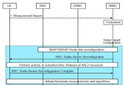
Figure 19 Reconfiguration to DCH9 EUL Mobility
9.1 General
This paragraph specifies the mobility cases when EUL is used. EUL can be configured per RBS to use either 10 or both 10 and 2 ms TTI, and when 2 ms TTI EUL is used there are special mobility cases described below.
The HSDPA and EUL Serving Cells are always the same, and the serving cell change is performed for both HSDPA and EUL at the same time. The serving cell controls the UL and DL data transmission and schedules the rates and the users. EUL is always used together with HSDPA, it cannot be used stand-alone. When EUL/HSDPA is active, all cells in the active set must support EUL/HSDPA. When EUL with 2 ms TTI is used, all cells in the active set must support this. The combined mobility functionality of HSDPA phase 1, phase 2 and EUL is described below. Cell Change is triggered by the same triggers as when only HSDPA is used. It can be divided into the following parts:
- E-DCH soft/softer HO.
- Serving E-DCH/HS-DSCH Cell Change triggered by change of “Best Cell” within the Active Set.
- Serving E-DCH/HS-DSCH Cell Change triggered by removal of the serving E-DCH/HS-DSCH cell from the Active Set.
- Leaving EUL coverage.
- Coverage triggered IF or IRAT HO attempts.
- E-DCH/HS-DSCH Cell Selection. This can be triggered at RAB establishment or by activity, (throughput measurement).
Transitions from EUL/HSDPA to DCH/DCH requires that the feature HS mobility phase2 is active.
9.1.1 Iur support
EUL/HSDPA and soft/softer HO for E-DCH is also supported over Iur. It is possible to perform a serving E-DCH/HS-DSCH Cell Change to or between external DRNC cells, and to perform upswitches from DCH to EUL/HSDPA over Iur. The DRNC cells must be EUL/HSDPA capable and correctly defined in the DRNC, and the following related SRNC parameters must be configured, both for the Iurlink and for External Utran cells:
ExternalUtranCell parameter cellCapability, hsdschSupport = On, edchSupport/ edchTti2Support = On
Iurlink parameter cellCapabilityControl, set per DRNC, hsdschSupport = On, edchSupport/ edchTti2Support = On
Iurlink parameter hspaPathlossThreshold applies for cell selection for DRNC cells
RNC parameter hsToDchTrigger, changeOfBestCellInterRnc applies for reconfigurations to DCH for DRNC cells.
Note that for external DRNC cells over Iur, both a coverage relatation and a neighbour relation must be defined to support Cell Selection.
9.1.2 E-DCH Soft/softer HO
When EUL/HSDPA is active, all cells in the active set must have the same EUL/HSDPA capability at all times, also regarding 2 and 10 ms TTI for EUL. Soft/softer HO for E-DCH works as normal rel99 DCH soft/softer HO, and the same parameters are used for the various events. The difference is that a non-EUL capable cell is never included in the active set while EUL is used, and the same applies for a non-2ms-TTI-EUL capable cell when 2 ms TTI EUL is used. An event report that is proposing to add a cell with the wrong capability to the active set is then ignored, and the cell is not added.
Eventually other conditions might trigger a reconfiguration. If the neighbor cell with the wrong capability is later reported strong enough by the periodic event reports, so that the calculated event 1d-RNC is triggered, the connection shall be reconfigured, thereafter the cell shall be added/replaced into the active, see below. Admission control for the new link is performed before adding a E-DCH RL. The maximum active set size that can be used with EUL is 4.
In order for soft/softer HO to work over Iur for DRNC cells the hsdschSupport and edchSupport/edchTti2Support parameters must be set to On for the Iur link cellCapabilityControl parameter.
If soft/softer HO triggers a removal/replacement of the serving cell from the active set, then a serving Cell Change will first be performed, thereafter the cell can be removed.
9.1.2.1 Resource blocking
2 ms TTI EUL requires more RBS HW than 10 ms TTI EUL, and is more likely to be blocked by admission control. If the connection is using 2 ms TTI EUL and an RL add is blocked due to UL HW limitations in Admission control, the connection shall be switched to 10 ms TTI EUL. If this switch fails, the connection shall be switched to DCH/HS. Repeated RL add attempts might then later be admitted.
9.1.3 E-DCH/HS-DSCH Cell Change
The serving E-DCH/HS-DSCH Cell Change procedures will try to keep the best cell in the active set as the E-DCH/HS-DSCH serving cell. CPICH quality measurements for all active set cells are used to determine which cell is the best cell and trigger a serving Cell Change, that is event 1d HS. A Cell Change can also be triggered if Soft/Softer Handover removes the current serving cell from the active set. A serving E-DCH/HS-DSCH Cell Change can only be performed to a “Suitable E-DCH/HS-DSCH cell”, which means a cell in the active set that supports HSDPA and EUL. Note that while using E-DCH/HS-DSCH, all cells in the active set support both HSDPA and EUL at all times, and also the same EUL TTI. The UE measurement quantity used to define the best cell is controlled by the parameter hsQualityEstimate, and hysteresis and time to trigger values can also be set separately for the event 1d HS. This means that Cell Change triggered by change of best cell can be tuned without affecting soft/softer HO. If a serving E-DCH/HS-DSCH Cell Change attempt fails, a fallback to DCH is normally attempted instead.
When a serving E-DCH/HS-DSCH Cell Change is triggered by change of best cell, that is event 1d HS, then RNC will take the following steps:
- If the parameter hsCellChangeAllowed is TRUE, a valid target cell evaluation is performed within the current active set. If the parameter hsCellChangeAllowed is FALSE then continue at step 4 below.
- RNC then selects the best of the active set cells. It has to be an E-DCH/HS-DSCH capable and enabled cell, and it must be better than the current serving cell by hsHysteresis1d/2. If an active set cell is a DRNC cell over Iur then hsdschSupport and edchSupport/edchTti2Support must be set to On for the Iurlink cellCapabilityControl parameter. If these conditions are fulfilled then a Suitable EUL/HS cell is found.
- If a Suitable EUL/HS cell is found the serving E-DCH/HS-DSCH Cell Change execution starts. First Admission Control is performed for the EUL part. RNC will then change the serving cell for both the HSDPA part and the EUL part at the same time.
- If the Cell Change cannot be done, that is if Admission Control blocks, if the parameter hsCellChangeAllowed is FALSE, or if no Suitable EUL/HS cell is found, or if the Cell Change execution fails and the connection does not drop, then an attempt to reconfigure to DCH shall instead be made. The reconfiguration to DCH also requires HS mob 2 licence. If the connection is using 2 ms TTI EUL and the Cell Change is blocked by the admission check for eulServingCellUsersAdmTti2 in the target cell, the connection shall be reconfigured to 10 ms TTI EUL and the Cell Change is re-attempted.
- RNC checks the parameter hsToDchTrigger and if the transition to DCH is allowed for the case “changeOfBestCellIntraRnc”. This parameter can be set to ON or OFF separately for different cases that can trigger transitions to DCH. If an active set cell is a DRNC cell over Iur, then the case “changeOfBestCellInterRnc” instead applies. If this transition to DCH is allowed then continue, otherwise RNC takes no more actions.
- RNC then attempts a downswitch to DCH, to a connection not using E-DCH/HS-DSCH. If the transition to DCH is blocked by Admission Control or fails then no more actions are done.
- If the parameter hsCellChangeAllowed is TRUE, a valid target cell evaluation is performed within the current active set. If hsCellChangeAllowed is FALSE then continue at step 4 below.
- RNC then selects the best of the other remaining active set cells that supports E-DCH/HS-DSCH. It has to be an E-DCH/HS-DSCH capable and enabled cell and it must be better than the current serving cell by hsHysteresis1d/2. If an active set cell is a DRNC cell over Iur then hsdschSupport and edchSupport/edchTti2Support must be set to On for the Iurlink cellCapabilityControl parameter. If these conditions are fulfilled then a Suitable EUL/HS cell is found.
- If a Suitable EUL/HS cell is found then the serving E-DCH/HS-DSCH Cell Change execution starts. First Admission Control is performed for the EUL part.
- If the Cell Change cannot be done or is not allowed, that is Admission Control blocks or no Suitable EUL/HS cell is found, or if hsCellChangeAllowed is FALSE or if the Cell Change execution fails and the connection does not drop, then RNC will attempt to reconfigure to DCH. The reconfiguration to DCH also requires HS mob 2 licence. If the connection is using 2 ms TTI EUL and the Cell Change is blocked by the admission check for eulServingCellUsersAdmTti2 in the target cell, the connection shall be reconfigured to 10 ms TTI EUL and the Cell Change is re-attempted.
- RNC then checks the parameter hsToDchTrigger and if the transition to DCH is allowed for the case “servHsChangeInterRnc” or “servHsChangeIntraRnc”. The first case applies when the best cell is an external cell in another RNC, the second case applies when the best cell is an intra-RNC cell. This parameter can be set to ON or OFF separately for different cases that can trigger transitions to DCH. If the transition to DCH is not allowed then the connection shall be released.
- Attempt a downswitch to DCH, to a connection not using E-DCH/HS-DSCH. If the transition to DCH is blocked by Admission Control or fails then RNC shall release the connection.
9.1.4 Leaving EUL coverage
When an EUL user drives into a cell where the same EUL capability is not supported, the connection must first be reconfigured in UL so that the cell then can be added to the active set. This is triggered by monitoring 1a and 1c event reports requesting to add the cell with the wrong capability to the active set. If event1dRncThreshold number of event1a and/or event1c reports are received requesting to add the same cell with the wrong capability, and where all the reports are event1dRncOffset stronger than the current serving cell, then the reconfiguration in UL is triggered, followed by adding/replacing the cell to the active set.
Case1: The connection is using EUL but the target cell is not EUL capable. When event 1d-RNC triggers, the connection shall be switched to DCH/HS, and then soft/softer HO shall execute the latest 1a or 1c report and add or replace the non-EUL cell to the active set.
Case2: The connection is using 2 ms TTI EUL but the target cell is not 2 ms TTI EUL capable, (but it is 10 ms TTI EUL capable). When event 1d-RNC triggers, the connection shall be switched to 10 ms TTI EUL, and then soft/softer HO shall execute the latest 1a or 1c report and add or replace the target cell to the active set. If the switch to 10 ms TTI EUL fails, the connections shall be switched to DCH in UL.
The sensitivity of this trigger, that is how long the original connection is kept, can be adjusted with the parameters event1dRncThreshold and event1dRncOffset. If the switch to DCH in UL is blocked by Admission Control or fails the connection is released.
Also note that a non-EUL cell that is reported in a 1a or 1c report as stronger than the active set plus releaseConnOffset parameter will cause a drop, since it cannot be immediately added to the active set.
9.1.5 Coverage Triggered IF or IRAT HO attempt
The connection quality monitoring using events 2d, 2f, 6d and 6b is used to detect bad quality in UL or DL when using EUL/HS-DSCH. If bad connection quality (event 2d or 6d) triggers while the connection is on EUL/HS it is checked if the licence “IF/IRAT Mobility on HSDPA/EUL” is active, or if 2 ms TTI EUL is used.
Licence available:
If the licence is active and 2 ms TTI EUL is not used, and then an IF or IRAT HO attempt might start, refer to Section 5.2. If neither IF or IRAT measurements can be started the UE will remain on EUL/HS.
For an IFHO attempt, when a 2b report is received, IFHO can only be executed if the target cell has the same capabilities regarding HS and EUL as the current connection. If the reported IF candidate cell does not support these capabilities then a switch to DCH/HS or DCH/DCH shall be done before the handover can be executed. If these reconfigurations fail or cannot be done, then no more actions are taken, the UE will continue with compressed mode and measurements until the quality gets good, or until another event-report is triggered
Licence not available:
If an event 2d or 6d is triggered when using EUL/HSDPA and the licence “IF/IRAT Mobility on HSDPA/EUL” is not available, then the License Key for “HSDPA Mobility phase 2” is checked and the parameter hsToDchTrigger is checked for the case poorQualityDetected. If both are allowed then the switch to DCH shall be attempted. The internal variable ConnQual shall then be set to “bad connection quality” after the reconfiguration. If this transition to DCH is not allowed or if the transition is blocked by Admission Control or fails no other actions are done. When the connection has been reconfigured to DCH an IF or IRAT Handover attempt might start.
9.1.5.1 Bad Coverage Triggered while using 2 ms TTI EUL
If bad connection quality (event 2d or 6d) triggers while the connection is using 2 ms TTI EUL, compressed mode is not supported.
Poor DL Coverage
If event 2d (poor DL quality) is received and the feature “IF/IRAT Mobility on HSDPA/EUL” is active, a reconfiguration from 2 ms TTI EUL to 10 ms TTI EUL shall occur and then start of Compressed Mode. Should the reconfiguration from 2 ms to 10 ms TTI fail, the connection shall be reconfigured to DCH/DCH. If the license “IF/IRAT Mobility on HSDPA/EUL” is not activated the reconfiguration shall instead be made to DCH/DCH. When reconfigurations have been performed to a state where compressed mode is supported, IF or IRAT measurements might start as described elsewhere.
Poor UL Coverage
At the detection of high UE output power (event 6d) for the RAB combination with 2 ms TTI EUL a reconfiguration to the same RAB combination with10 ms TTI EUL shall be triggered. The assumption is that a switch to 10 will improve the UL coverage.
9.1.6 E-DCH/HS-DSCH Cell Selection
E-DCH/HS-DSCH Cell Selection can be triggered at RAB establishment of a PS interactive connection, by an upswitch attempt from FACH, or by a throughput-based activity trigger for an already established PS interactive connection on DCH. The procedures will then check which is the highest capability cell that is available in the order of EUL/HSDPA, DCH/HSDPA, DCH/DCH, and then try to setup or reconfigure the connection there. First it is checked if the best cell in the active set is EUL/HSDPA capable, if not then as a second step it is checked if there is a coverage related cell to the best cell that is EUL/HSDPA or DCH/HSDPA capable. If an EUL capable cell is found, a setup using 2 msTTI EUL is preferred if this is supported. When the Cell Selection has been triggered then RNC will take the following steps:
- If it is an activity triggered upswitch, not from FACH, then check that the connection quality is good in both UL and DL, which means that the corresponding events 2d and 6d have not triggered. If quality is good, the upswitch to EUL/HSDPA is always allowed. If the quality is bad, the upswitch to EUL/HSDPA is only allowed if the license “IF/IRAT Mobility on HSDPA/EUL” is active, ie HO attempts are allowed while on EUL/HSDPA. Check if the UE supports EUL/HSDPA. If an active set cell is a DRNC cell over Iur then hsdschSupport and edchSupport/ edchTti2Support must be set to On for the Iur link cellCapabilityControl parameter.
- RNC then checks if the best cell in the active set has E-DCH/HS-DSCH support. If the UE has an active set with more than one cell, then also check that all cells in the current active set support EUL.
- If YES then reconfigure the connection to E-DCH/HS-DSCH, with the best cell as serving E-DCH/HS-DSCH cell. 2 ms TTI EUL shall be used if this is supported.
- Otherwise RNC will check if the parameter hsOnlyBestCell = FALSE, which means that selection of a cell other than the best cell is allowed. This selection is not done from DCH/HSDPA, only from DCH/DCH. Then check if the best cell instead has a coverage related cell that supports E-DCH/HS-DSCH and where the coverage indicator is set to Covers or Overlap. Note that the coverage relation can only be between cells in the same RNC, and that defining this relation means that the cells have the same coverage so that it is safe to perform a blind HO.
- If it is an upswitch attempt from FACH, then the connection can be reconfigured directly to EUL/HSDPA in the target cell. The FACH state is not supported over Iur.
- If it is not an upswitch from FACH, then a hard HO must first be performed to the coverage related cell before the connection can be reconfigured to E-DCH/HS-DSCH, if this cell is not included in the active set. First a pathloss check is performed, the current pathloss is calculated and compared with the parameter hsPathlossThreshold. If an active set cell is a DRNC cell, then a separate hspathlossThreshold parameter is used, defined per Iurlink. If the current pathloss is higher than this threshold then RNC will take no more actions. If the coverage related cell is already part of the active set, then reconfigure to E-DCH/HS-DSCH with the coverage related cell as the new serving cell.
- Otherwise RNC will perfom a hard HO on DCH to the coverage related cell, keeping the same RAB configuration. Then reconfigure to E-DCH/HS-DSCH with the new cell as serving E-DCH/HS-DSCH cell. 2 ms TTI EUL shall be used if this is supported.
10 Core Network Hard Handover
Core Network Hard Handover can be split into 3 main parts:
- Measurement Handling for Core Network Hard Handover The measurement handling algorithm prepares the list of cells that the UE will measure on. It requires a new cell concept called 'Non-Iur External' cell.
- Core Network Hard Handover Evaluation The evaluation algorithm performs the cell selection when a 'Non-Iur External' cell candidate exist. The evaluation part is further split between Intra-frequency cell selection and inter frequency cell selection.
- Core Network Hard Handover Execution In the execution phase the source RNC requests the core network to set up resources in the target RNC for a core network handover. The UE is then moved to the target RNC (the actual handover takes place).
10.1 Measurement Handling for Core Network Hard Handover
Measurement Handling for Core Network Hard Handover requires a new cell concept defined in UTRAN, called 'Non-Iur External' UTRAN cell, see Section 3.2 Measurement Handling (Meas_Handl).
The Measurement Handling feature only requires measurements in Cell_DCH state. The target cell selection is based on the existing Soft Handover Evaluation and Inter Frequency Handover Evaluation: for both cases, the ’Non-Iur External’ cells will be included as any other 'Normal' UTRAN cell (that is cells belonging to the same RNC or to RNCs’ towards which an Iur interface is configured) in the Monitored Set sent to the UE in the MEASUREMENT CONTROL message.
- Note:
- The Core Network Hard Handover feature can be defined when the SRNC does not have any Iur connectivity configured towards the target RNC (The Iur link must however be defined due to Ericsson implementation). A DRNC, on the other hand, could have an Iur connectivity configured towards the target RNC. The Core Network Hard Handover can be enabled or disabled to a specific RNC by defining or not defining the target RNC as an external RNC in the source RNC, and by setting the cnhhoSupp parameter to TRUE.
Intra Frequency Handover
The Measurement Handling is based on the constraint that the ’Non-Iur External’ cells, now belonging to the Monitored Set, can never be included in the Active Set. Consequently the ’Non-Iur External’ cells will cause 1a, and 1c event triggered periodical reporting, while 1d events will be reported more than once in general but not periodically. Moreover, when cell lists are truncated due to more than 31 neighbors, according to the existing algorithm, 'Non-Iur External' cells will be treated as any other neighboring cell.
The outcome of the MEASUREMENT REPORT, will be evaluated by the Intra Frequency Core Network Hard Handover Evaluation located in the Serving RNC, where a target cell selection is performed.
Inter Frequency Handover
The Measurement Handling uses the same quality supervision events for starting and stopping Compressed Mode as for 'Normal' Inter Frequency Handover. When cell lists are truncated due to more than 32 neighbors, according to the existing algorithm, 'Non-Iur External' cells will be treated as any other neighbors cell.
The outcome of the MEASUREMENT REPORT , will be evaluated by the Inter Frequency Core Network Hard Handover Evaluation located in the Serving RNC, where a target cell selection is performed.
10.2 Core Network Hard Handover Evaluation
The Core Network Hard Handover Evaluation consists of a target cell selection based on the output of the Core Network Hard Handover Measurement Handling. The evaluation is performed in the Serving RNC.
10.2.1 Intra Frequency Core Network Hard Handover Evaluation
The Intra-Frequency Core Network Hard Handover is triggered when no soft/soft handover candidate exist and the Non-Iur External’ cell quality compared with the quality of the current Active Set cells, fulfils the following condition:
External-cell quality level > M + intraFreqCnhhoPenalty, (1),
where M is a weighted sum of the quality level of the current Active Set cells according to the ‘weighting’ parameter intraFreqCnhoWeight, and intraFreqCnhhoPenalty is a parameter (in [dB] unit) that introduces a ‘penalty’ when ’Non-Iur External’ cells are compared to 'Normal' cells in the current Active Set.
The quality level of the current Active Set cells introduced in M, can be based on either Ec/No (no unit) or RCSP ([mW] unit) measurements; according to that, the measurement quantity used in (1) for External-cell quality level and M, must be [dB] unit or [dBm] unit respectively.
M is used for all the relevant measurement reports indicating addition, replace and change of the best cell (i.e. for 1a, 1c and 1d events) when comparing Non-Iur External cells with current Active Set cells, to reflect that situations with many cells in the Active Set together may contribute to a good quality of the connection. The parameter intraFreqCnhhoWeight is a scale number that defines the weight of the radio links in the Active Set. If it is set to 0, only the best cell in Active Set is considered, otherwise, if it is set to a value grater than 0, all radio links in the Active Set are considered. Finally in case of setting to 1, all radio links in the Active Set are given equal importance.
According to the parameter intraFreqCnhhoPenalty, the 'Normal' cells can be always prioritized before the ’Non-Iur External’ cells.
If an event 1a, 1c or 1d is received, and both the 'Normal' Intra Frequency handover criterion and the criterion (1) above are fulfilled at the same time, it will be evaluated if a Soft/Softer handover (based on the reported 'Normal' cell) or a Hard handover (based on the triggered 'Non-Iur External' cell) will be made. The' Normal' cell has to be included in a fictive Active Set (if the Active Set already is full, the worst cell must be removed from the fictive Active Set); the triggered 'Non-Iur External' cell is compared with the weighted sum of the fictive Active Set cells, according to the criterion (1). If the criterion (1) is still fulfilled, then a Intra-Frequency Core Network Hard Handover is performed, otherwise the RNC triggers a normal Intra Frequency Handover.
10.2.2 Inter Frequency Core Network Hard Handover Evaluation
The Inter Frequency HO evaluation including ’Non-Iur External’ cells is started if hoType / defaultHoType is set for Inter Frequency Handover for at least one of the cells in the active set.
The ’Non-Iur External’ cells must be included as any other IFHO cells in IFHO monitored set; in that way, RNC triggers Inter Frequency Core Network Hard Handover if the reported cell in the event 2b, belongs to the ’Non-Iur External’ cell group.
The RNC triggers Inter Frequency Core Network Hard Handover in case of:
- Only ’Non-Iur External’ cells are reported in 2b event and the measurement report does not contain any information on IFHO 'Normal' cells.
- The event 2b is triggered both for 'Normal' and ’Non-Iur External’ cells, but the quality level of ’Non-Iur External’ cells is a relative threshold level stronger ( interFreqCnhhoPenalty) than any IFHO 'Normal' cells reported in 2b event, according to the following condition (in [dB unit]): External-cell quality level > Best IFHO + interFreqCnhhoPenalty
The parameter interFreqCnhhoPenalty introduced in case 2, defines a ‘penalty’ in order to make it possible for the operator to prioritize the 'Normal' cells with respect to the ’Non-Iur External’ cells. The parameter interFreqCnhhoPenalty is intended to be either interFreqCnhhoPenaltyEcno or interFreqCnhhoPenaltyRscp, depending on which evaluation is ongoing.
In case 1 the ‘penalty’ is not used because only ‘’Non-Iur External' cells are triggered for the event 2b (not repeated periodically) and there is no comparison with 'Normal' cells.
10.3 Core Network Hard Handover Execution
The source RNC triggers an Intra Frequency or an Inter Frequency handover Execution to a ”Non-Iur External” UTRAN cell, see Section 3.2 Measurement Handling (Meas_Handl), under the condition that the Core Network Hard Handover function is enabled, that is when cnhhoSupp is set to TRUE, and the target RNC is defined as external RNC in the source RNC.
In the Core Network Hard Handover Execution phase, the target RNC allocates resources when requested by the CN. It performs the complete mapping from RAB parameters down to physical layer configuration in a way similar to RAB establishment. The target RNC must be able to cope with source RNCs from other vendors, implementing e.g. re-starting UE measurements and establishing SRB4 if it is not established prior to the Hard Handover via the CN.
Core Network Hard Handover can only be executed for UEs using Circuit-Switched services. If the UE only uses Packet Switched services and is in Cell_DCH state, the Source RNC will instead trigger Directed Signaling Connection Re-establishment, forcing the UE to re-establish with the network. If the UE uses both Circuit Switched and Packet Switched services simultaneously, the source RNC will release the Packet Switched service and trigger the Core Network Hard Handover for the Circuit Switched service. If only a Circuit Switched Signaling connection is established, the Core Network Hard Handover Execution is not initiated.
Note that for the case with PS services when Direct Signaling Connection Re-establishment is used, the functionality is still limited by the 3GPP standard and UE behavior. After the release the UE will first try to camp in the frequency that the UE just released. The cell camping procedure will be completed based on cell selection criteria. If the criteria is fulfilled, UE sends RAU request to resume PS data. If UE cannot camp on the cell due to cell selection criteria failure, the UE will scan for other frequencies.
10.3.1 Actions taken by Core Network Hard Handover
The case is initiated when SRNC detects the need to perform the Hard Handover via the CN into a cell in an RNC towards which no Iur connectivity is configured.
- The source RNC indicates to the MSC that Hard Handover is required.
- The MSC requests resources from the target RNC. If the Core Network Hard Handover function is enabled, the target RNC performs Admission Control based on the received RAB information and requests resources for the new RL from the target Node B.
- The target RNC responds to the MSC, providing the RRC message that will trigger the UE to switch to the target RNC.
- When the resources are allocated the MSC indicates to the source RNC that the preparation phase is completed (providing the RRC message received from the target RNC).
- The source RNC forwards the RRC message, received from the target RNC, to the UE. The UE changes to the configuration provided in the received RRC message; if the new configuration is on a new frequency the UE tunes to this frequency.
- Once the UE has changed to the new configuration, it responds to the target RNC accordingly to the previously received message.
- After a successful switch at the MSC, the MSC releases the resources in the source RNC.
- Note:
- Since the target RNC may be a non Ericsson RNC the received RRC message may be any of the messages RADIO BEARER, TRANSPORT CHANNEL, PHYSICAL CHANNEL RECONFIGURATION, RADIO BEARER SETUP or RADIO BEARER RELEASE.
Figure 20 shows the sequence messages between the UE and the WCDMA RAN, for the Core Network Hard Handover.
 Figure 20 Core Network Hard Handover Sequence
10.3.2 Exception Handling
If an Intra Frequency Core Network Hard Handover attempt fails it will not be repeated, a new attempt will be initiated at the next measurement event.
If an Inter Frequency Core Network Hard Handover attempt fails it will be repeated in the same way as for an Inter Frequency Handover. The number of repetitions will consequently be controlled by the parameter IfhoAmountPropRepeat.
11 Service-Based Handover
11.1 Description
This feature makes it possible to redirect speech users to GSM based on a Service Indicator (SI) that can be used per subscriber. This gives the operator the possibility to prioritize between subscriptions. The operator can even use it in order to “only” use UMTS for other services than speech (e.g. reuse of the existing GSM NW) The main goal of the Service Based HO is to be able to “send” UEs with SI=”should” and RAB combination = “Speech only” to GSM as soon as possible. After the RAB has been setup, if the SI = “should” and the RAB combination = “speech only”, the RNC sends a MEASUREMENT CONTROL to the UE, with trigger conditions for the existing Inter-RAT Handover functionality, that is GSM neighboring cell list, activation of Compressed Mode, GSM and UTRAN thresholds for event 3a. A high UTRAN threshold value is used as default, so that the UTRAN quality should always be fulfilled, and only the GSM target cell quality level is considered.
The SB HO attempt will be stopped by a timer if there are no suitable GSM cells and the event 3a is not triggered within a specific time.
The RAB Assignment Request is the first message from the CN that contains the RAB type and the Service Indicator (SI). First there is a check to see if the feature is supported (that is the Licence Key is available and active), and that the UE supports GSM Handover; if these conditions are not satisfied, the connection is treated as a “normal call”.
If these requirements are fulfilled, a check is performed to evaluate if GSM Handover is allowed for this RAB (by checking the constant C_gsmHoAllowed) and if Inter-RAT Handover is allowed (by checking the parameter fddGsmHoSupport). The Handover type is also checked: if the HO type is Inter Frequency or GSM preferred, then the user is a candidate for Service Based Handover, otherwise, if the HO type is “NONE”, the connection will be treated as a “normal call”. Finally the cell is checked to see if it has GSM neighboring cells.
If Connection Quality is bad and event 3a or event 2b has started, the connection will be treated as a normal handling; on the other hand, if event 3a or event 2b has not started, the connection will be treated as Service Based Handover connection.
Note that when a Service Based Handover connection is ongoing, Softer/Softer handover (that is event 1a, 1b, 1c and 1d) and Connection Quality Monitoring (that is event 2d and 2f) can be normally started, stopped and modified.
The MEASUREMENT CONTROL sent to the UE contains:
- GSM neighboring cell list, as for normal Inter-RAT Handover.
- Activation of Compressed Mode.
- Gsm threshold ( gsmThresh3a).
- UTRAN modified threshold ( C_utranThresh3aForcedGsm). Ec/No measurements are always used.
11.2 Service Based Handover Execution
Service Based Handover Execution performs the Execution part of the Inter-RAT Handover algorithm ordered by the SBHO Evaluation, when the event 3a is triggered. During the SBHO Execution phase, the Compressed Mode must be allowed by the Admission Control; also a timer is started in order not to let the UE to be in Compressed Mode for too long.
The source RNC triggers Service Based Handover Execution if the SBHO function is enabled, i.e if the License Key is available and active.
11.2.1 Interactions with Other Functions
This feature is based on the existing coverage triggered Inter-RAT Handover functionality. If triggered, SB HO will instead be ongoing for a specific time after call setup, until the timer expires or until the SB HO to GSM is done.
Inter-Frequency Load-Sharing takes place at RRC connection request, (i.e. before the connection is identified to be a candidate for Service Based Handover). Users can be moved to another frequency due to load sharing and from that frequency make a Service Based Handover to GSM.
Load sharing via directed retry to GSM takes place at RAB Assignment Request, (i.e. before the RAB is setup). The existing Load sharing via directed retry to GSM is not modified.
11.2.2 Actions taken by Service Based Handover Execution
The case is initiated at the end of Service Based Handover Evaluation phase (i.e. when the RNC has checked that the SI is “should” and the RAB combination is “speech only”). After having sent the RAB Assignment Response, the RNC has sent a MEASUREMENT CONTROL, to the UE with the GSM neighboring cell list, activation of Compressed Mode (if needed), GSM ( gsmThresh3a) threshold and UTRAN ( C_utranThresh3aForcedGsm) threshold.
A timer is started, in order not to let the user to be in Compressed Mode for too long time (if it can’t find a suitable GSM cell).
The Execution part of Inter-RAT Handover ordered by Service Based Handover takes place, i.e. event 3a is received. The connection has established a GSM connection, i.e. successful Service Based Handover. The timer is stopped.
Figure 21 gives an overview (in terms of sequence messages between the UE and the WCDMA RAN) of the Service Based Handover sequence phases.

Figure 21 Service Based Handover Sequence11.2.3 Exception Handling
Before SBHO Execution, if the UERC state changes, i.e. an incoming packet data call takes place (Multi RAB state) or the speech RAB is changed to SRB during Service Based Handover measurements, the timer is stopped.
If the Inter-RAT Handover Execution ordered by Service Based Handover fails (e.g. due to GSM capacity problem), the RNC will try, during the timer length, to handover the connection to GSM. If the IRAT HO doesn’t succeed during the timer length, the timer expires and the Service Based Handover is stopped.
At the expiry of the timer, the Connection Quality is checked:
- If the Connection Quality is 'good', the Service Based Handover measurements is stopped. The UE hasn’t succeeded to find a GSM cell (i.e. Service Based Handover failure) and UTRAN will not ask for a second SBHO for this user. This call will be treated as a “normal call” . This user will be a target for coverage triggered IRAT HO if the connection quality degrades.
- If the Connection Quality is 'bad', the HO type is checked again due to the fact that the UE can have changed cell. If the HO type is “GSM_PREFERRED” the user will continue in Compressed Mode and the MEASUREMENT CONTROL (containing the thresholds used for coverage triggered IRAT HO measurements) is sent to the UE. (i.e. utranThresh3a is used instead of C_utranThresh3aForcedGsm).
If the HO type is “IFHO_PREFERRED”, Compressed Mode is modified for Inter Frequency Handover, i.e. GSM measurements are stop and Inter Frequency Handover measurements are started.
If the HO type is “none”, Service Based Handover measurements are stopped.
12 Engineering Guidelines
- Note:
- Product Description Information The Engineering Guidelines are not completely updated to the current product release described in this document.
The purpose of this section is to provide additional information on how to use parameters to achieve certain behaviors, while highlighting possible unexpected effects. With a WCDMA frequency reuse of 1 the cell plan, power settings and proper neighbor cell lists are more important than in GSM.
The following factors are crucial for good handover performance: cell plan, neighbor lists, setting of handover parameters, common and dedicated channel power settings and UE performance.
The handover performance should be monitored as traffic grows. Example of KPIs to monitor are: drop rate, average and distribution of number of active radio links, active set update rate, size of handover area.
12.1 Soft/Softer Handover
12.1.1 Cell Plan Importance for Handover Behavior
A good cell plan and correctly defined neighbor cells are the foundation for good handover behavior.
Areas with many equally strong CPICHs, so-called “pilot pollution areas”, should be avoided. Preferably only one dominant CPICH should exist. UEs in pilot-polluted areas may experience unreasonable high Active Set update rates and a higher probability that the Active Set does not at all times contain the most appropriate cells. With extensive pilot pollution in the system the signaling load increases. Pilot pollution gives a high average number of active radio links, which decreases the traffic capacity and reduces the probability that the UE gets all neighboring cells included due to the size limited monitored set.
It is recommended to design the system so that the idle mode cell selection/reselection borders coincide with the connected mode HO borders.
It is also recommended that the CPICH power setting initially balances the UL and DL in the handover area. A balanced system in this context means that the pathloss is equal at the handover borders for every cell to be included, or are already included in the Active Set. The handover areas and where the handover decisions are taken can be changed by changing CPICH power levels for the cells. After initial tuning to have an initially balanced system, activities can be pursued to tune the pilot setting according to coverage or traffic distribution.
12.1.2 Determining Neighbor Cell Lists
Neighbor cell selection should be made with care in the WCDMA RAN. There is a restriction of the number of neighbors that can be monitored. Superfluous neighbors should not be defined. On the other hand, all true neighbor cells must be defined. A UE will approach an undefined neighbor cell without adding it to the Active Set, and will therefore not be power controlled by the cell. If the UE comes close to an undefined neighbor, it will cause destructive interference that in the worst case leads to dropped calls. Neighbor definition based on field measurements is recommended.
The UE measures the cells in the Monitored Subset list, see Figure 3. The maximum number of WCDMA RAN cells in Monitored Subset is 32, including the cells in the Active Set.
When the union of the neighbor cell lists for the cells in Active Set is made, that is, when creating the Monitored Subset, there are typically a number of duplicate cells. These are removed and thus do not occupy any space in the monitored subset. But the risk remains that some neighbor cells are excluded from the Monitored Set when the Active Set contains many cells, since the maximum limit may be exceeded. Therefore, it is important to define only the appropriate neighbors, and carefully prioritize all neighbors. This is another reason to avoid pilot pollution as far as possible. Since the greater the cells that are present in the Active Set, the fewer the number of neighbors per cell that will be included in the Monitored Subset. Furthermore, it is desirable to avoid coverage islands from distant cells.
As a rule-of-thumb, each cell should not have a number of neighboring cells exceeding 17–20. However, in an area where the number of duplicate cells is large for the cells in the most likely Active Sets and the Active Sets typically contain few cells, then more than 20 neighbors can be used without significant performance impact. Note that one property of the reduction algorithm is that if cells have a large difference in the number of neighbors, for example, Cell A = 32 and Cell B = 10, all of equal importance, Cell A with the most neighbors will be penalized relative to Cell B by the reduction since Cell B be will get all neighbors into the monitored set, but only a subset of Cell A's neighbors will be included.
If the number of neighbor cell relations needs to be so large that truncation becomes a problem, it is possible to control the order in which the neighbor cells are included. The RNC picks the neighbor cells to be included in the Monitored Subset list in the same order as stored in the RNC. This makes it possible to control the probability for a certain neighboring cell to be included. The order in which neighboring cells are stored can be controlled by configuring the list of ordered neighbor cell relations for a cell using an MO script. Note that if a new cell relation has to be added to an existing list then the entire list has to be deleted first and then re-created.
Note that with the introduction of priorities for neighbor cells ( selectionPriority), this attribute can instead be used to define the order. The use of neighbor prioritization can make it possible to exploit the advantage of long neighbor lists while still limiting the negative effects of truncation. By prioritizing the neighbors already when sites are brought on air, the truncation risk can be managed and the most important neighbors can be ensured not to be exposed to truncations. First, the method to avoid missing neighbors by generously selecting neighbors is applied. Then the 15 most important neighbors are selected and assigned a higher priority than the remaining neighbors. With a maximum of 15 high priority neighbors it can be guaranteed (with very few exceptions) that they will not experience truncation. Hence, there is no need to individually prioritize among these 15 neighbors. For the remaining neighbors, further prioritization could be necessary. This may be the case if the radio environment requires many neighbors and the number of obvious neighbor candidates exceeds 15. There is no advantage in individually prioritizing all neighbors for each cell. The approach should instead be to prioritize groups of neighbors, all for the purpose of making the neighbor planning phase easy and efficient.
It should also be noted that if a missing neighbor cell is reported as a detected cell by the UE when this cell was previously reduced from the monitored set, Ericsson WCDMA RAN is capable of including the cell in the Active Set. However, the UE delay performance for reporting detected cells may vary and the UE is allowed to have longer delays than for Monitored Set reporting.
If the UE performance for detected cells is known to be in parity with the UE performance for monitored cells in a network, the list can be longer and the order is less significant.
12.1.3 Reducing Dropped Calls
Dropped calls can be reduced by tuning the soft/softer HO parameters statistically for each RNC. The optimal setting of parameters like reporting-ranges, time-to-triggers, and hysteresis values can be slightly different from one RNC to another, depending on the general radio environment and traffic behavior.
A missing neighbor cell might cause dropped calls. If the UE detects interference from an unknown cell that is stronger than the current Active Set + releaseConnOffset parameter, then the call will be released. Therefore it is important to define all relevant cells as neighbors, so that they can be added to the active set by soft/softer HO.
If an already defined neighbor cell, that is stronger than the current active set + releaseConnOffset parameter, cannot be added to the Active Set for any reason, then the call will also be released. This could, for example, be caused by congestion in a high traffic situation.
Areas with coverage or interference problems can also cause dropped calls. A poor radio environment can block signalling to and from the UE and cause Active Set update procedures to fail, which will generate dropped calls.
12.1.4 Soft/Softer Handover Parameters
The recommended setting of parameter maxActiveSet is 3. Increasing the value leads to an increase in the average number of active radio links. The difference will be minor in some areas, whereas in areas with many strong CPICHs, the average number of active radio links will increase considerably. In UL more active radio links on average gives a slightly lower transmitted power. In DL more active radio links gives a lower transmitted power for each link, but the sum of transmitted power on active links might not be lower.
The number of Active Set updates per minute is dependent on the radio environment and there is no direct relation to the setting of parameter maxActiveSet.
The size of the soft and softer handover area can be changed by parameters reportingRange1a and reportingRange1b. The recommended parameter values are 3 dB and 5 dB, respectively. Increasing the value for parameter reportingRange1a or reportingRange1b results in larger soft/softer handover area, that is, more UEs will be in soft/softer handover on average. The average number of active radio links in the network can grow very large when increasing the value for parameters reportingRange1a and reportingRange1b.

Figure 22 Active Set Distribution with Different Size of the Soft Handover Area. Example from Field Measurements.


No comments:
Post a Comment